We’ll get into more detail about the steps of wiring and finalizing the Cube Pro printer in this section. A lot of questions were asked and we’ll do our best to clarify what’s not clear with the previous blog parts.
You can read the previous blog parts here:
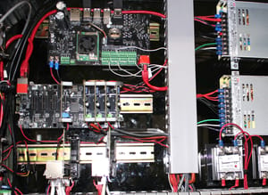
Detailed wiring
Refer to the following link for a detailed step-by-step guide for wiring the Duet Wifi: https://duet3d.dozuki.com/Guide/2.)+Wiring+your+Duet/9
Please refer to the following table for various connection information:
| Duet Output | Duet Input | Sensor | Power Circuit | Source | |
| Bed | HEATED BED | THERMISTOR0 | Thermistor built-in | SSR | AC Voltage |
| Heated environment | E1 HEATER | E1 THERMISTOR2 | 300°C thermistor | Relay | AC Voltage |
| DyzEnd | E0 HEATER | E0 THERMISTOR1 | 500° thermistor | Duet Mosfets | DC Voltage |
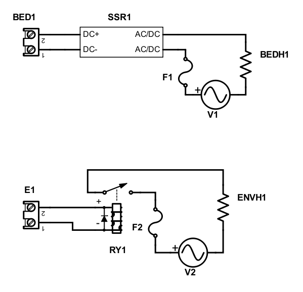
Here is a diagram for connecting the AC voltage to the bed heater and chamber heater:
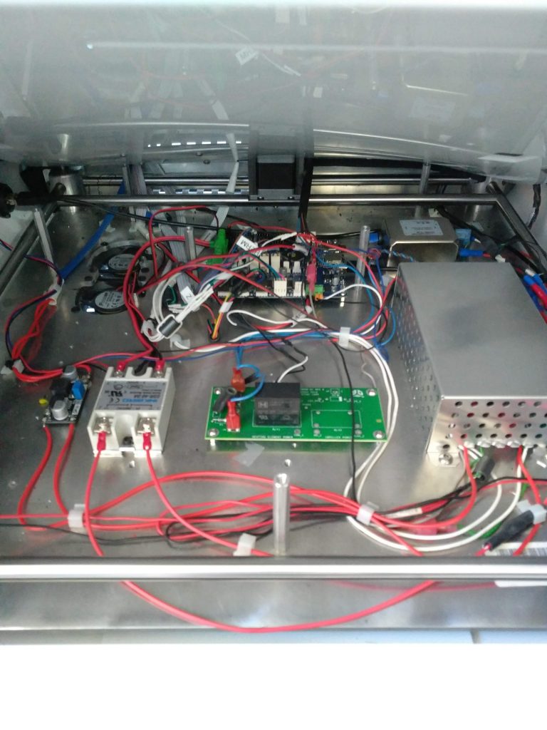
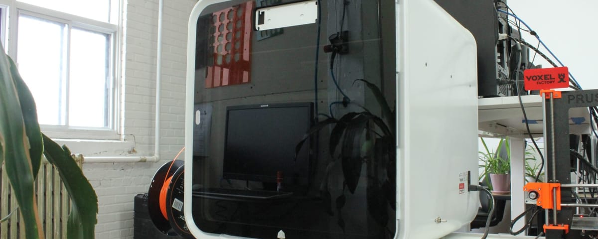
Here is our final wiring once everything is done:
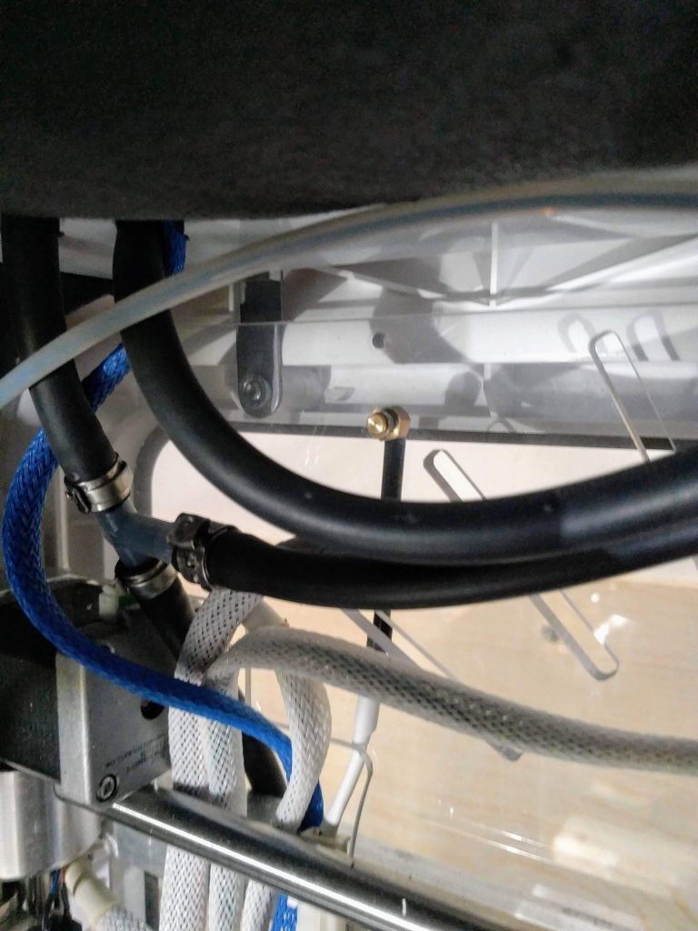
Environment sensor
We used our M5 threaded sensor for monitoring the environment. It’s a 100K NTC thermistor. We drilled a hole in the acrylic and threaded it.
Cables
For most cables, we did our best to use the stock cables. For most of them, we changed the connectors so they can fit with the Duet.
Conclusion
We will continue to edit this particular blog section with further clarifications if need be.
Also, feel free to send us some pictures of your own Cube Pro conversion, we will share them!

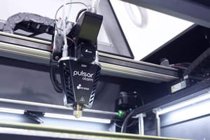
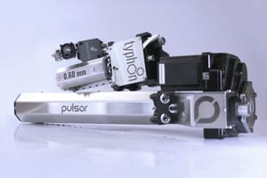

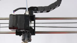


43 Comments
just wondering, I have one of these. will the duet board power the massive z axis motor or did you add an external driver. what are the current requirements for that one
The Duet is very capable. Our Z motor is currently running at 800mA and everything works well.
Is possible to have more photo or one video for cow to connect all the cable to the logic board ?
Nicola, I think it is possible, but I don’t believe it could be clearer than the schematic drawings we made. Cables come from all around and are difficult to track.
Can you please post a wider shot of the finished conversion? I’m interested in how the external radiator is mounted. Where did you put the reservoir?
Hi Rob,
The external radiator has been mounted on an acrylic plate, not tied to the 3D Printer. We let it sit on the top. You can check our suggested part for the reservoir and radiator set-up.
Is there any chance that you develop a kit with all the components required so we can purchase it from you?
Unfortunately, since the CubePro is a retired product, the investment of time and resources in such kit would not worth it.
Any videos of the completed project in operation? I’m in the middle of a CubeX Dual (similar to the Cube Pro) conversion.
Sadly not at the moment! However, we are getting a set of cameras, and we should be able to make video very soon!
Can you share the prints of this machine, I wonder how does it print after the conversion?
Can you share the prints of the machine, I wonder how well does it print after the conversion?
Sure! I’ve taken a not about making videos and pictures. I think I’ll dedicate a 5th blog part for these.
I’m looking forward for it. 🙂
I agree with the B Gray, videos will help. Thanks for your blog, after reading it i decided to buy a cube pro.
good morning,
Can you tell me how to lure the recognition chip from the pro cube cartridges, to use standard filament spools. The cube pro cartridges are no longer sold and too expensive.
Hi Eric. Sadly, we are not experts at hacking the original system. The simplest solution is to remove all electronic components and start fresh as we suggested in our blog.
You can refill the cartridges.
http://www.print3dforum.com/showthread.php/1712-Building-Tomuro-s-Circuit?highlight=Tomuro
In looking at your pictures I did not see any of the part cooling fans reinstalled. Did you reinstall them? On my CubePro I have 3 of them two in the front and one in the rear.
One more question. On my cubePro the 2 cooling fans that are on the bottom of the unit, that cool the electronic, are wired directly to the power supply. I assume they must be 24V? If that is the case were all the fan 24V?
Thanks,
Randy
No, we didn’t reinstall these fans. We wanted to use the cube pro for high temperature materials and they usually don’t need any cooling.
As far as I remember, these two fans were 12V wired in series.
Hello,
There are dual y-axis motors in cube pro printer.I measured motors connections,and turned out that are connected in parallel.I think well and are connected to “Drive1 Y motor” and only change is in cable connector compatible for duet board?
Exactly. This is what we used to do.
Up to recently, everything was fine. However, we started having skipping along the Y axis.
We ended up rewiring each motors individually, the 2nd Y motor wired on the 2nd extruder output.
I’m evaluating the purchase of a duet 2 wifi and i want to figure this problem before buying so to keep the second extruder free to use. Correct me if i’m wrong, the two y motors are wired in parallel, the driver then should provide 2 times the current of one motor to run both, but in the driver setting i see I=1500 mA. Is this a mistake? Reading on duet guide it seems better to connect the motors in series using the given connectors on the duet, due to lower current you have less heat dissipation. Have you ever tried this?
Good observation, Alessandro.
We set the current at 1500mA, and the current per motor is indeed much lower than the specified one by the datasheet. However, for this printer, having two motors to move the axis is a little bit overkill, and running them at lower current is totally fine. By using this setting, we make sure the driver isn’t overheating, and we don’t get any missing steps.
Philippe,, I have most of the wiring done following your blog as the guide. I used your Duet config file to get the Duet Wifi configured. I was wondering what slicer you are using and if you will be willing to share the profile for the slicer. I have no problem using a different slicer for this printer. I am current using Simplify 3D for my other printer.
Thanks,
Randy
We are using Prusa Slicer. We used Simplify3D in the past, but it seems like this paid software is falling behind the open source software.
Philippe, can you tell me how to disassemble the x-cariage, I need to take off some metal from the barings to fit a Hemera between them,
Thanks,
Marcel.
Taking out the bearing is quite a tedious job…
You need to remove the whole frame body from the white case, then you’ll be able to dismantle the carriage and remove those bearings.
I already did this but I don´t see any designated screws that hold the corners connected to the rods, as I don´t want to damage anything I thought you know how to remove them maybe you like to share this whith me.
I’m very sorry Marcel, we have started this project 3 or 4 years ago, and we don’t have many pictures. It’s very hard for me to remember the exact procedure for taking apart the bearings from the carriage…
The bearings are simply pressed in. So you could take them out and put them in using something like a small arbor press
Amazing, I would love to visit you guys someday since I am in Laval…
BTW : First link is broken…
Thanks for pointing that out, the link should be fixed!
I am doing exactly the same, But I found that I have a lot of issues with vibrations. My prints tends to unstick. I believe it is because I make my testing out of the plastic casing, but have you had any of these kind of issues?
Vibration will be reduced with acceleration tuning. Try lower values.
To make sure the print sticks, use larger line thickness for the first layer, slower, and hotter bed.
Philippe, I am using your 500C extruder. I noticed at room temperature the extruder sensor bounces around a bite. With the chamber heated up it appears to stabilize once it reaches around 110C. The bed heater and the chamber heaters are working perfectly. It is this behavior expected with the 500C extruder ? I attached my config.g file below in case its a configuration issue. My config.g is based on the one you provided with some changes.
Thansk,
Randy
config.g
; Configuration file for Duet WiFi (firmware version 2.03)
; executed by the firmware on start-up
;
; generated by RepRapFirmware Configuration Tool v3.1.3 on Fri Jun 12 2020 20:17:53 GMT-0700 (Pacific Daylight Time)
; General preferences
G21 ; Work in Millimeters
G90 ; send absolute coordinates…
M83 ; …but relative extruder moves
M555 P2 ; Set firmware compatibility to look like Marlin
; Network
M550 P”CubePro” ; set printer name
M552 S1 ; enable network
M586 P0 S1 ; enable HTTP
M586 P1 S0 ; disable FTP
M586 P2 S0 ; disable Telnet
; Drives
M569 P0 S1 ; physical drive 0 goes forwards 1
M569 P1 S1 ; physical drive 1 goes forwards 1
M569 P2 S1 ; physical drive 2 goes backwards 0
M569 P3 S0 ; physical drive 3 goes backwards
M584 X0 Y1 Z2 E3 ; set drive mapping
M350 X16 Y16 Z16 E16 I0 ; configure microstepping with interpolation
M92 X87.90 Y87.90 Z1066.67 E592.35 ; set steps per mm
M566 X900.00 Y900.00 Z12.00 E120.00 ; set maximum instantaneous speed changes (mm/min)
M203 X15000.00 Y15000.00 Z1200.00 E1800.00 ; set maximum speeds (mm/min)
M201 X500.00 Y500.00 Z250.00 E250.00 ; set accelerations (mm/s^2)
M906 X1500 Y1500 Z800 E800 I30 ; set motor currents (mA) and motor idle factor in per cent
M84 S30 ; Set idle timeout
; Axis Limits
M208 X0 Y0 Z0 S1 ; set axis minima
M208 X280 Y295 Z190 S0 ; set axis maxima
; Endstops
M574 X1 Y2 S0 ; set active high endstops
M574 Z1 S2 ; set endstops controlled by probe
; Z-Probe
M558 P5 H5 F120 T6000 I1 ; set Z probe type to effector and the dive height + speeds
G31 P500 X-52 Y-8 Z0.45 ; set Z probe trigger value, offset and trigger height
M557 X0:275 Y27:255 S20 ; define mesh grid
; Heaters Bed
M305 P0 T97968 B4630 C9.486166e-8 R4700 ; set thermistor + ADC parameters for heater 0
M143 H0 S280 ; set temperature limit for heater 0 to 280C
; Heaters Hot End
M305 P1 T4606017 B5848 C5.548428e-8 R4700 ; set thermistor + ADC parameters for heater 1
M307 H1 A580.4 C256.6 D6.4 S0.50 B0 ; Disable Big Bang
M143 H1 S480 ; set temperature limit for heater 1 to 480C
M570 H1 P4 T25 ; Allow 25C varation from setpoint
; Heaters Chamber
M563 H2 P5 S”Chamber Heater” ; Set Tool 5 to set Chamber heater in S3D
;M141 H2 ; assign chamber heater to heater 2 – Removed to set Chamber heater in S3D
M143 H2 S120 ; set temperature limit for heater 2 to 120C
M307 H2 A50 D60 B1 ; Enable Big Bang
M305 P2 T97968 B4630 C9.486166e-8 R4700 ; set thermistor + ADC parameters for heater 2
; Fans
;M106 P0 S0 I0 F500 H-1 ; set fan 0 value, PWM signal inversion and frequency. Thermostatic control is turned off
M106 P0 S0 I0 F500 H1:2 T200 ; set fan 0 value, PWM signal inversion and frequency. Thermostatic control is turned off
M106 P1 S0 I0 F500 H1:2 T200 ; set fan 1 value, PWM signal inversion and frequency. Thermostatic control is turned off
M106 P2 S0 I0 F500 H1:2 T200 ; set fan 2 value, PWM signal inversion and frequency. Thermostatic control is turned off
; Tools
M563 P0 D0 H1 F0 ; define tool 0
G10 P0 X0 Y0 Z0 ; set tool 0 axis offsets
G10 P0 R0 S0 ; set initial tool 0 active and standby temperatures to 0C
; Custom settings
; Filament Sentinel
M591 D0 P1 C3 S1 ; Filament Sentinel
;M581 T1 E0 S0 C0 ; filament Sentinel
; Miscellaneous
M911 S10 R11 P”M913 X0 Y0 G91 M83 G1 Z3 E-5 F1000″ ; set voltage thresholds and actions to run on power loss
thanks,
Randy
Philippe, Sorry about the formatting above. I am using your 500C extruder. I noticed at room temperature the extruder sensor bounces around a bite. With the chamber heated up it appears to stabilize once it reaches around 110C. The bed heater and the chamber heaters are working perfectly. It is this behavior expected with the 500C extruder ? I attached my config.g file below in case its a configuration issue. My config.g is based on the one you provided with some changes.
Thanks, Randy
Yes, this behavior is totally normal. The temperature bounce you see at room temperature is caused by a poor resolution at low temperature from the sensor we use. The hotter it gets, the better the resolution. Its peak point is actually at printing temperature, which is good.
Philippe, I am testing my newly rebuilt printer. I am struggling a little with print quality. I noticed you stated that you are using PrusaSlicer. Would you be will to share an export of your PursaSlicer configuration?
Thanks,
Randy
Sure! Here is our ini file:
# generated by PrusaSlicer 2.2.0+win64 on 2020-10-25 at 00:32:45 UTC
bed_custom_model =
bed_custom_texture =
bed_shape = 0x0,280×0,280×271,0x271
before_layer_gcode =
between_objects_gcode =
cooling_tube_length = 5
cooling_tube_retraction = 91.5
default_filament_profile = “”
default_print_profile =
deretract_speed = 0
end_gcode = M104 T0 S0 ; turn off top extruder\nM140 S0 ; turn off bed\nG91\nG01 Z1.0 F300\nG90\nG01 X0 Y0 F6000\nM84 ; disable motors
extra_loading_move = -2
extruder_colour = “”
extruder_offset = 0x0
gcode_flavor = reprap
high_current_on_filament_swap = 0
host_type = octoprint
inherits =
layer_gcode =
machine_max_acceleration_e = 1000,5000
machine_max_acceleration_extruding = 1000,1250
machine_max_acceleration_retracting = 1000,1250
machine_max_acceleration_x = 3000,1000
machine_max_acceleration_y = 3000,1000
machine_max_acceleration_z = 25,200
machine_max_feedrate_e = 100,120
machine_max_feedrate_x = 400,200
machine_max_feedrate_y = 400,200
machine_max_feedrate_z = 8,12
machine_max_jerk_e = 2.5,2.5
machine_max_jerk_x = 4,10
machine_max_jerk_y = 4,10
machine_max_jerk_z = 0.1,0.4
machine_min_extruding_rate = 0,0
machine_min_travel_rate = 0,0
max_layer_height = 0
max_print_height = 190
min_layer_height = 0.07
nozzle_diameter = 0.7
parking_pos_retraction = 92
print_host =
printer_model =
printer_notes =
printer_settings_id =
printer_technology = FFF
printer_variant =
printer_vendor =
printhost_apikey =
printhost_cafile =
remaining_times = 0
retract_before_travel = 2
retract_before_wipe = 0%
retract_layer_change = 0
retract_length = 1
retract_length_toolchange = 10
retract_lift = 0.25
retract_lift_above = 0
retract_lift_below = 0
retract_restart_extra = 0
retract_restart_extra_toolchange = 0
retract_speed = 40
serial_port =
serial_speed = 250000
silent_mode = 0
single_extruder_multi_material = 0
start_gcode = M104 T0 S[first_layer_temperature]\nG28 ; home all axes\nM109 T0 S[first_layer_temperature]\nG92 E0\nG1 Z0.5 F300\nG1 X10.0 Y10.0 F9000.0 ; Go at starting point\nG1 X160.0 E30 F600.0 ; Prime Line 0.40 x 1.20\nG92 E0\nG1 E-1.0;
thumbnails =
toolchange_gcode =
use_firmware_retraction = 0
use_relative_e_distances = 0
use_volumetric_e = 0
variable_layer_height = 1
wipe = 1
z_offset = 0
Hello Philippe,
Jason here form New Zealand and Formtech, a new Dyze reseller ( yet to get going with you), I rebuild Cube pro machines here and have started a Cube rebuilders grouup if you are keen to join??
is at:
https://www.facebook.com/groups/756881225011365
or via http://www.formtech.co.nz and the blog post https://www.formtech.co.nz/blogs/news/supercharged-3d-systems-cube-pro-trio-totally-rebuilt-into-a-high-end-production-printer
cheers
jason
Hello everyone,
Thanks to Philippe for his write-up on his conversion process. I was lucky enough to find a cubepro next to my apartment’s dumpster, and have begun the process of taking it apart for a conversion. I have ordered the customized parts as mentioned in the blog (build plates, heaters, and the carriage plate); and have one extra set available if someone else is looking to do the conversion and would like an arrangement that would reduce costs for both of us.
I also noticed there were quite a number of fasteners required, both at the bottom of the cubepro, as well as on the sides (near the metal plates) and around the metal shroud housing the power connector. I found it easier to turn the cubepro on the side and lift the outside aluminum composite case, rather than try to move the inner assembly upright. Be careful not to damage the space heater fans located between the outer frame and plate (that electronics are sitting on).
Although my experience in 3D printing is limited, I am happy to respond to questions that people might have regarding the cubepro conversion process (especially as Philippe’s memory is probably strained at this point with so many years passing). If you would like to reach me feel free to send me an email (agaboowu a t gmail).
Thanks again to Philippe and the community for publishing information about this printer and how to improve it. Without it, Dyze would probably be short an order from me, but also this beautiful piece of hardware would have probably wound up in the dump.
I have a CubePro Duo that I wouold like to upgrade. Bought in 2012 but basically unused.
You mention you bought a spare set of parts for the upgrade.
Do you still have any of those parts like the heated pad?