

Choosing the right speed for your print can be quite a challenge, especially if you are new to 3D printing. After a bit of trial and error, you’ll be able to guess a setting that will generally work. Still, you’ll have a lot of variation with your results. Finally, you might not be using your hardware at its full potential by randomly choosing values.
The print speed calculator has been developed to help you choose the right setting based on our experimental values. This blog will teach you the basics for understanding 3D printer extrusion, how we developed the calculator and why it can be very useful for you.
Using the right line width
Line width is a critical parameter for a successful print. Most software will generally calculate it automatically, but you’ll soon realize it’s much better to configure it by yourself.
The slicer’s automatic calculation consider the nozzle size and increase it by 20%. A general rule of thumb accepted by 3D printer users suggest a line width up to 50% bigger than the nozzle. Although this generally works fine in most cases, you’ll see a big drop in print quality and consistency with bigger nozzles and layer height.

Understanding the extruded profile
The molten plastic is pushed in something like an oblong shape. For simplifications, we’ll consider a perfect oblong shape. This flattening ensures a good bond between the layer underneath or the bed. Extruding a perfect circle would make very weak since each layer would barely be touching each other.

Too small line width
This oblong radius is equal to half the line height. The radius is changing with the layer height. The higher the layer height, the larger is the radius. At some point, the traditional 20% increase in line width can’t cut it and will under-extrude. Under extrusion happens when there is little to no line flat from the extruded oblong. The figure below shows an example where the extrusion has no flats. In this configuration, the layer height is equal to the line width. The line flat is equal to zero.

Minimum line width
The minimum line width can be considered when the flat width is equal to the nozzle size. This ensures that the oblong shape is properly formed and uniform.

For example, a 0.40mm nozzle with a 0.20mm should have a line width of at least 0.60mm.
The figure below shows a minimal configuration for line width.
Please note that the line width could actually be a little smaller than this suggested formula. The shape will slightly differ from the perfect oblong shape depending on the polymer flow. In most cases, a smaller line width is totally fine.

Maximum line width
The maximum line width will depend on your nozzle flat width. Manufacturers should specify this dimension to configure your slicer accordingly. The maximum line flat should be equal to the nozzle flat. Note that any overflow will have an impact on top infill quality, as it will tend to rise around the nozzle.

Considering a 0.40mm nozzle having a 0.80mm flat with a 0.20mm layer thickness have a maximum line width of 1.00mm.

The myths about layer height
It’s common to see that 50% of your nozzle size is the sweet spot for printing. This works totally fine in most printing situations. It’s also very frequent to hear that it’s not good or possible to go higher in layer height than the nozzle diameter.
Going bigger!
However, nothing is stopping you from going a lot higher or lower. For example, the two images below are the same exact Gcode, one ran with a 1.00mm nozzle, the other with a 0.40mm nozzle. The line height is 0.50mm and line width is 1.50mm.


As you can see, there is barely any difference. As long as the 0.40mm nozzle flat is within the margin, the result is pretty good. In this case, the layer height was 125% the nozzle diameter.
Smaller nozzle can still extrude large lines, but have more flow restrictions compared to larger nozzles. The speed must be decreased to get the same results.
Going smaller!
A similar test was done using a 1.00mm nozzle, but with 0.05mm layer height. In this set-up, the layer height is only 5% of the nozzle size. The results are quite interesting. The picture below shows a 20mm diameter half-sphere side by side with an AA battery. The zoom is pretty high, and we still have a hard time seeing the layers.

Printing with such a big nozzle reduces your detail level on the XY plane compared to a smaller nozzle. However, the line are very thick, thus greatly reducing the infill and contour printing time.
Choosing the right flow
Choosing the right flow will save you a lot of trial and error before getting consistent results. Polymer flow variation can be understood in the following way:
- Increasing the line width, height or speed will increase flow
- More flow means that the polymer is less time in the melting zone, thus extruding slightly colder
- Combining the lower temperature and the higher shear stress generates a higher pressure
- A higher pressure puts more stress in the filament and extruder
- At some point, either the motor will start missing steps or the filament will grind, and the extrusion is not controlled anymore
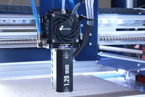
There is always a small slipping in the filament from the extruder. The faster you go, the greater is the slipping. Below is an example taken from the DyzEnd-X with few nozzles. You can see that the 1.20mm nozzle can output a lot more flow than the other nozzles. Also, the efficiency is decreasing by an exponential rate based on the output flow.

Taking this into account, it’s very important to choose the right speed and flow to get the same output. For example, doubling the flow from 5 mm3/s to 10mm3/s can reduce flow by around 3%. Same case with a 0.60mm nozzle will reduce flow by 2%, and less than 1% with a 1.20mm nozzle.
Flow calibration
Flow calibration is critical and the steps per mm must be precisely found. The values provided by the guide in support section gives a starting point. Due to manufacturing tolerance, this value can be different from one unit to another. It is suggested to calibrate your extruder without any hotend, as a baseline value for any users.
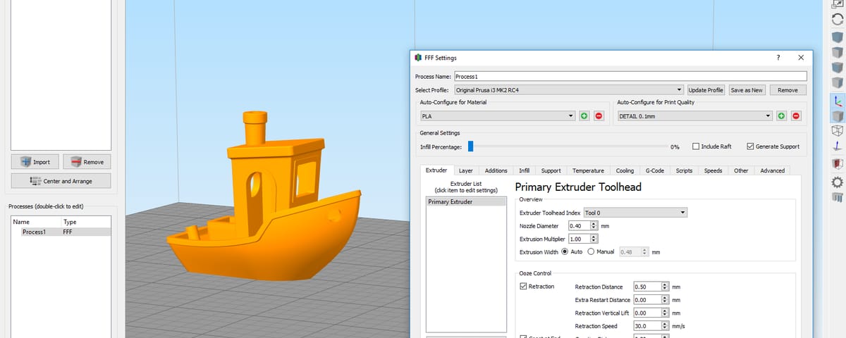
The print speed calculator

With all this knowledge, it’s now time to introduce the speed calculator. The goal of this tool is to offer the most precise slicer configuration for your 3D printer. The data comes from multiple experimental tests in different configurations:
- Nozzle size
- Material
- Temperature
- Hotend
- Extruder
All these results were broke down into charts which are used in this calculator. Once you enter the desired layer parameters, the maximum printing speed is calculated. From this point, the user can choose a lower value if desired. The suggested flow is then adjusted based on the slower speed.
This flow adjustment is critical for dimensional accuracy. The pressure is reduced as the speed is farther from the maximum, thus requiring a slightly lower flow. Keeping the same flow for different speed might lead to a small difference in dimensions.
Printing with large nozzles can confuse some users as the speed might seems slow. In fact, when using a 1.00mm nozzle with a 0.50mm layer height and 1.50mm line width, the suggested speed is below 35mm/s. Many users would be tempted to guess this speed at a much higher value.
The experiments are still undergoing and the calculator will be improved with more choices and more precise values.
Conclusion
Choosing the proper parameters for speed and flow is quite an art. There are many rules of thumbs for helping in this task. However, as shown in this blog, they might not always be right or the optimal solution.
The print speed calculator has been developed for helping users defining their optimal speed and flow. This will greatly help improve part accuracy and consistency across materials and configurations.
I hope you enjoyed this article about this new tool. I’ll be happy to complete it if I have forgotten or mistaken any information. Feel free to comment it and share your thoughts.
34 Comments
The problem is, choosing an extrusion width also affects how slicers slice thin walls. If you’re printing a part with thin infill or walls, some lines may start dropping out of the sliced model. If you have a line width of 0.6 mm and you have a 1 mm wide wall, then only 1 perimeter would get printed.
That’s right. Let’s hope someday the slicer will be able to manage a variable line width, this would help in many situations.
Great explanation. Philippe, what formula do you use in the calculator?
Hi Viacheslav,
The formula used is simply the oblong area times the speed to calculate the volumetric output. The maximum value is obtained experimentally.
We are building a 3D food printer. And we are using a gear pump to pump food to the dispenser. The problem is we have no idea on how to control the dispenser (i.e. to close and open ). We haven’t decided on the dispenser we gonna use. Any idea ? Would really appreciate your response.
Hi Nzuzo,
Sadly, since we haven’t designed the extrusion system, it’s very hard for us to suggest anything regarding the dispenser opening and closing.
How about an X cut in a thick layer of silicone? Like how those ketchup bottles work these days? Without pressure, the toughness of the silicone keeps it closed. Upon adding pressure, the 4 flaps open..
Very interesting article, it sure brings down some taboos.
But in the case of going with a layer height higher than nozzle size, what would be a formula for maximum layer height?
Thanks!
In theory, it should look like “Nozzle Flat” – “Nozzle size”. I haven’t made tests with the highest layer, it could be an interesting next blog.
Can you consider updating this outstanding tool to be compatible with other 3d printing materials like abs and petg?
Of course! It’s a work in progress, testing all the materials and the nozzles sizes take quite some time 😉
Four years and no new materials added to the menu.
Thanks for pointing that out Guy!
We took some time and updated the values for all the polymers we tested, it should be greatly helpful now!!
Thanks for all your work!
Very interesting.
How about retraction? No bad influences to retraction performance?
The retraction hasn’t been tested here. We only studied the optimal printing speed.
Don’t understand the calculator. You always talk about optimal print speed. But i get maximum speed with the calculator. I don’t need Maximum speeds i want optimal print speed
The optimal speed is sensitive to your application. Knowing the maximum speed is a good start as most people were going over the extrusion system limit.
Anything below the maximum speed can be optimal.
Thank you for this great article!
I’m having a hard time trying to understand what “nozzle flat” is and how to figure it out or estimate it. I searched online and couldn’t find a mention of it except here. Not even your TC nozzle page mentions this value. All I understood is it’s not the nozzle’s orifice diameter. Could you please explain what it is and how to calculate/estimate it?
The nozzle flat is the larger diameter around the nozzle orifice. It can be measured or can be checked with online drawings.
Would this mean that having a nozzle with a very narrow flat, i. e. the coned shape starts almost immediately outside the extrusion hole, would constitute a bad nozzle design for nozzles determined for thick lines? As there’s almost no flat to “iron” the top of the oblong shape..
I have just tried a cheap chinese 0.6mm nozzle in my Ender-5 Plus – which is due for a direct extruder and a tripling of frame size – and it has a flat less than 0.9mm across the hole. Results were bad, to put it short.
Should I chuck it up in the lathe and machine it to a 1.2mm wide flat, maybe?
Yes, exactly. I can’t remember where I saw this, but there is an article about the line shape depending the the height and width. Once the polymer is not guided with the flat, it’s going to raise above the nozzle height.
Could worth a try, if you want to get thick lines, that sounds like a good solution. Make sure you aren’t removing too much!
Hi Phillippe,
How does volumetric output play in the calculation of speed? I’m most curious as to how a super volcano hot end could print faster than a volcano hot end with similar nozzle diameters. Also, with a 1.4mm nozzle being available for the SV, is there a reduction in speed over the smaller nozzles? I don’t quite understand how a less restricted flow could result in a slower speed. Thank you for this article, I reference it regularly.
Good question, Niktron. The volumetric flow is directly related to speed. If you increase layer height, you need to reduce the speed, to keep the flow equal. If you increase the flow over the recommendation, you’ll see under-extrusion or extruder skipping.
Reaching a certain nozzle size, the nozzle back pressure becomes irrelevant. The only important factor is how you can heat the polymer. This is where extrusion length becomes interesting.
Thanks philippe,
By extrusion length do you mean the length of the heater block?
Yes, the length where the polymer is heated and inside the extrusion system (before it exists the nozzle)
Thanks for the great article.
For the minimum line with case, You said that ” In most cases, a smaller line width is totally fine. “. What did you mean by that?
For example, 0.4mm nozzle diameter with 0.2mm layer height correspond to 0.6mm minumum layer height. So 0.5, 0.4, 0.3mm can be applicable for the case? How much it can be smaller 🙂 ?
By smaller, we mean smaller than the line we suggest. For example, many people will use a line width of 0.48mm for a nozzle of 0.40mm. Please note that using a smaller line width than the nozzle size will lead to very poor result.
It’s up to you to test the limits of your printer, polymer and extrusion system.
Thanks to Philippe for the great article.
I have one question about the extruded profile. The profile looks exactly like being consisted of one rectangle plus two semi-circles.
But do you have any references or established theories that can explain why the edges of the profile can be considered as a semi-circle? (although it looks exactly like a semi-circle)
Look forward to your comments.
Best regards
Apart from my experiments and picture, I don’t have any other source.
I remember seeing an article about similar tests done when printing larger than the nozzles, but I couldn’t find it.
Very interesting article! I like the idea to challenge common rules of thumbs like “Layer height should be 50% of the nozzle size” and “line width up to 50% bigger than the nozzle”. Never understood where those rules were coming from. As en engineer myself, I really like your scientific approach.
I did some testing with my E3D V6 and this looks very promising. I am using a line width of 1.5 mm, a layer height of 0.5 mm and a print speed of 20 mm/s. Which slicer do you use? I am currently using Cura but I do not understand it. In Cura, the default line width is set to the nozzle diameter. But I am not sure how Cura actually computes the flow rate and what assumptions are made regarding the shape of the extrusion . Should I set the linewidth in Cura to 1.5mm? Or switch to another slicer?!
Thanks for the kind comments! This blog has been very interesting to do as I was very impressed by the results.
We currently use PrusaSlicer and Cura internally. I suggest setting the line width to 1.50mm.
Thank you for the information. I found this article at the right time. I’m currently having some small issues with warping. Do you know of a good starting point for diagnostic purposes? I’m making essentially 4 separate rectangles @22mmx110mmx60mm each. I have been using ½” aluminum strips to add additional heat after it has printed 2-3mm, which has helped. But I still am getting warp. Any tricks or help you can offer would be greatly appreciated. Also, being a fellow drummer, not sure you’re genre, but check out a song called Hot Like Sauce-Pretty Lights. One of my favorites to jam to while breaking in my new Alesis Studio Kit Pro
Hey Daniel! Usuaklly warping can be helped with the following:
– Increase bed temperature
– Add brim, but I personnaly prefer mouse ears
– Increase environment temperature
– Use a material that is known for warping less
– Use a fiber reinforced material
Very nice song BTW! Indeed different to what I’m used to, but there is a very nice groove in there, I can understand you enjoy jamming to it!