In this third and final part, we’ll be working on the heat bed, the controlled environment and finally the configuration for our Duet.
Heated bed
The heated bed was quite a challenge. The original “Print Pad” design is simply a glass plate with a 3mm plastic sheet glued over it. It works well with PLA, but anything else is very hard to stick. Even PETG wouldn’t stick. It was crucial to add a heated bed.
The original plate was easy to remove from the z-axis. We really liked this feature and wanted to keep it. The bottom had a big locating cylinder which seats in a triangular hole, on the Z axis system. 3 magnets secure the bed in place.
1. First test – Keep the glass bed
At first, we wanted to keep it as is. The glass plate was well designed with rounded corners and magnets. It would save us a lot of time not rebuilding the same setup.
Heating Pad
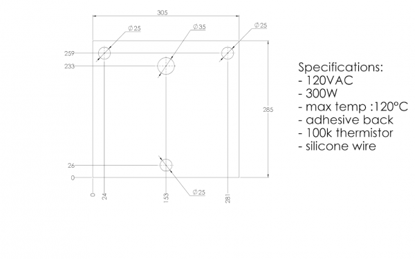
We contacted a silicon heating pad company for a customized design, hoping for a low MOQ order. We sent the following requirements at first:
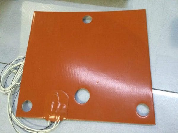
After some discussion, we ended up asking for a 3 wire setup. This enables us to wire it for 240VAC and 120VAC. This 3 wire set-up separate the heating pad in 2 resistance. Wiring them in series increase the resistance and is proper for 240VAC. Wiring them in parallel reduce the resistance and is proper for 120VAC.
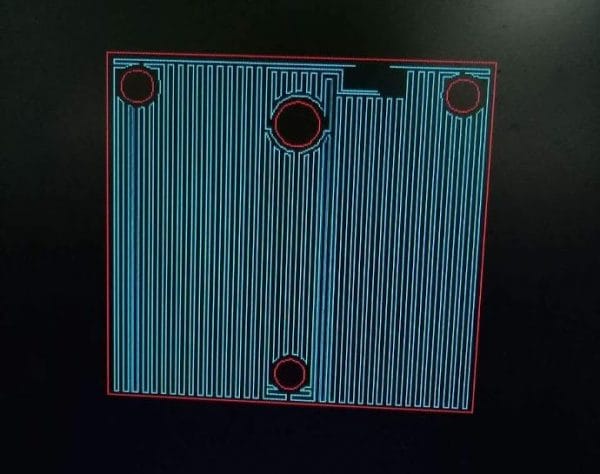
The actual resistance path looks like a sliced layer. You can see the 4 wires (two will be merged together for one wire) and an empty space for the thermistor.
We were pleased to find a company willing to do a customized heater for a single unit at a reasonable price. They offered a great service and the heated pad was shipped quickly. They offered to make this pad available on their store, you can find it here: https://www.aliexpress.com/store/709519
Spring connector
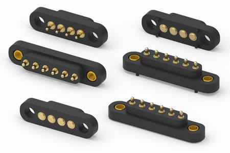
As the bed was very easy to install and remove, we wanted to keep it that way for the electrical connections too. We found Mill-Max, a company specialized in high-reliability connectors. Their spring-loaded connectors were perfect for our situation.
As we couldn’t thread in the glass, we machined an aluminum block and glued it using high-temperature epoxy.
Sadly, the epoxy wasn’t holding well. We tried to clean the surface, sand it, glue it again, and it wouldn’t stick.
The pivot movement required for removing the build plate was putting a lot of stress on the glue. We had to put the spring loaded connectors away for now and use a standard high-temperature connector.
Heating problems
We printed for a while using the original bed and it went well. But I’m sure you know what’s is going to happen once we start cranking up the heat. We had to increase the bed temperature for a high-temperature polymer in particular and something happened…
The plastic on top of the glass started warping and ungluing itself. We have reached the limit of this bed and now it is not usable anymore.
2. Second test – Use aluminum tooling plate
Unless you’ll want to stick with low bed temperature (<70°C), it is strongly advised to upgrade it too.
There are two majors choices when looking for a flatbed:
- Metals
- Glasses
Glasses are more stable than metals in therm of thermal expansion. However, they are more fragile and also worse thermal conductors.
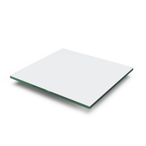
We have decided to choose what is called an “Aluminum Tooling Plate”. It’s a cast aluminum alloy milled for flatness. There are many registered names and alloys for this material and equivalents:
- Aluminum Jig Plate
- Mold Plate
- Alca 5
- ATP-5
- MIC-6
- 100S
- Alimex 5083
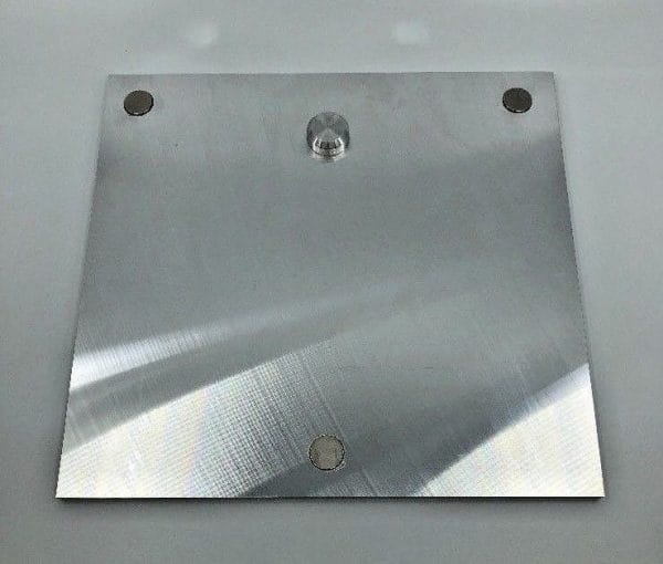
These plates are easy to find and easy to work with. It can be bought from a local store and cut to size. They can be machined and drilled, which is very useful for connectors, locating pins, magnets, etc.
The ebay seller “clay-nano-systems” sells aftermarket print bed for a very good price: https://www.ebay.com/itm/332983919976
It can be an interesting solution if you don’t want the hassle of machining the plate yourself. Our heated pad will work with this plate.
With this plate and a PEI tape bought from CS Hyde, we managed to print anything with great results.
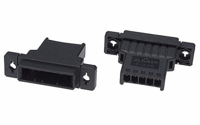
Standard connector
After the epoxy problem, we could have given a second try with the connectors, especially since they had mounting holes. However, we already had our alternative connector installed and decided to keep it there.
We opted for a TE Connectivity AMP Connectors Series Dynamic D-3100.
Controlled environment
The CubePro already has a good air heater for the environment. The housing is clean and elegant for an enclosed printer. We’ll give it a nice upgrade to make it even more reliable and efficient.
Cooling the components
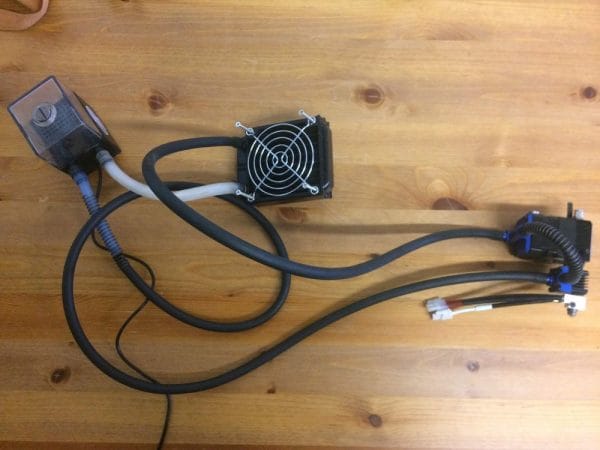
As mentioned before, the liquid cooling system will be keeping our critical components at a cooler temperature than the environment. Depending on your goal, it is not necessary to cool each axis motor.
Reaching temperatures higher than 70°C can be quite tricky as much more efforts will be required in the printer. Most cables, electronics, components will fail under higher temperature. A different printer design would be a better approach. For this printer, we’ll keep a 70°C goal.
Once you have decided which parts to cool, it is a good idea to run the loop first to ensure everything is working properly. It’s done very quickly and will save you a lot of trouble.
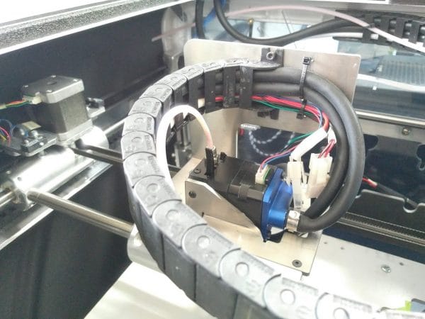
The tubes were installed inside the cable chain. There was enough space in the original cable chain for both liquid cooling tubes, plus the cables for the extrusion system.
Insulation
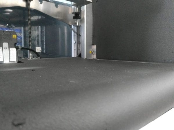
We added insulation to increase the efficiency of heating. Also, it helped to keep the electronic section cooler than the rest. We used Buna-N / PVC foam as the insulating material. The thickness is ½ inches. The maximum rated temperature is 105°C, which is more than enough for our application.
As installation tape, we used foam mounting tape from 3M, number 5952. It was rated for up to 120°C.
We added insulation throughout the printing zone, except for the back. This was only for preference, as the back could also benefit from additional insulation.
Configuration
You can check our configuration below for our Duet. The documentation is very well made and maintained.
Even if the Duet community doesn’t like our 500°C thermistor because it has poor resolution at room temperature ( we don’t print at room temperature ), we’ve got very nice prints quality and no trouble at all with any aspect of this printer.
; Configuration file for Duet WiFi (firmware version 1.17 to 1.19)
; executed by the firmware on start-up

; General preferences
M111 S0 ; Debugging off
G21 ; Work in millimetres
G90 ; Send absolute coordinates...
M83 ; ...but relative extruder moves
M555 P2 ; Set firmware compatibility to look like Marlin
M208 X0 Y0 Z0 S1 ; Set axis minima
M208 X280 Y295 Z190 S0 ; Set axis maxima

; Endstops
M574 X1 Y2 Z1 S0 ; Set active high endstops
M558 P0 H5 F120 T6000 ; Disable Z probe but set dive height, probe speed and travel speed
M557 X15:275 Y15:275 S20 ; Define mesh grid

;M581 T1 E0 S0 C0 ; Filament Sentinel

; Drives
M569 P0 S1 ; Drive 0 goes forwards
M569 P1 S1 ; Drive 1 goes forwards
M569 P2 S0 ; Drive 2 goes backwards
M569 P3 S0 ; Drive 3 goes backwards
M350 X16 Y16 Z16 E16 I0 ; Configure microstepping without interpolation
M92 X87.9 Y87.9 Z1066.67 E592.35 ; Set steps per mm
M566 X900 Y900 Z12 E120 ; Set maximum instantaneous speed changes (mm/min)
M203 X15000 Y15000 Z1200 E1800 ; Set maximum speeds (mm/min)
M201 X500 Y500 Z250 E250 ; Set accelerations (mm/s^2)
M906 X1500 Y1500 Z800 E800 I30 ; Set motor currents (mA) and motor idle factor in per cent
M84 S30 ; Set idle timeout

; Chamber
M141 H2 ; Assign chamber heater to heater 0
M143 H2 S100 ; Set temperature limit for heater 0 to 120C
M307 H2 A50 D60 B1 ; use bang-bang control for the chamber heater with 60 seconds dead time
M305 P2 T97968 B4630 C9.486166e-8 R4700 ; Set thermistor + ADC parameters for chamber

; Bed
M305 P0 T97968 B4630 C9.486166e-8 R4700 ; Set thermistor + ADC parameters for heater 0
M143 H0 S280 ; Set temperature limit for heater 2 to 280C

; Heater
M305 P1 T4606017 B5848 C5.548428e-8 R4700 ; Set thermistor + ADC parameters for heater 1
M307 H1 A580.4 C256.6 D6.4 S0.50
M143 H1 S480 ; Set temperature limit for heater 1 to 480C
M570 H1 P4 T25 ; Allow 25°C variation from setpoint

; Tools
M563 P0 D0 H1 ; Define tool 0
G10 P0 X0 Y0 Z0 ; Set tool 0 axis offsets
G10 P0 R0 S0 ; Set initial tool 0 active and standby temperatures to 0C

; Network
M550 PDyze Cube ; Set machine name
M552 S1 ; Enable network
M586 P0 S1 ; Enable HTTP
M586 P1 S0 ; Disable FTP
M586 P2 S0 ; Disable Telnet

; Fans
M106 P0 S0.3 I0 F500 H-1 ; Set fan 0 value, PWM signal inversion and frequency. Thermostatic control is turned off
M106 P1 S1 I0 F500 H1:2 T45 ; Set fan 1 value, PWM signal inversion and frequency. Thermostatic control is turned on
M106 P2 S1 I0 F500 H1:2 T45 ; Set fan 2 value, PWM signal inversion and frequency. Thermostatic control is turned on

; Custom settings are not configured
Leave us your comment
Thanks for reading this tri-part blog series. I really hope that we could help some of you with their printer conversion.
I’ll be happy to add any missing info. Simply leave us a comment and I’ll check for it.




55 Comments
Hi!
Thank you this blog series, it is very useful for me, because I make a same conversion on my CubePro Duo.
Can you give me a direct contact to the company who produced the silicone heating plate?
I send they a message in Aliexpress, but they don’t answer, and I don’t find this plate in their products.
I have one more question. Did you keep the original thermometer in the heated chamber?
I’m still waiting for some parts, but if I’m start a conversion, I’ll probably have a lot more questions.
Thank you!
Thanks for your feedback!
You can try contacting s at alirubber dot com, this is the contact we used to have.
We used a 300°C thermistor we had in stock, it has good resolution at 70°C.
Hi
Loved reading the blogs on this great conversion. Well done !
Am seriously considering following the steps here to upgrade a 3d printer with hopeful intention of ultimately printing Ulterm.
Have seen the video “DyzEnd-X Hotend Printing Demo in a CubePro 3d Printer” where its shown printing.
In the site store description, the DYZEXtruder rated for 500 degrees is “designed to work with any filament” It would be inspiring to see it in action printing filament at the top of the temperature range.
Just wondering If Is there a video, documentation available for public viewing showing that path has been beaten ?
I’d be more than happy to help you in this project.
We’ll definitely put some more time into generating content such as videos and picture of high-performance polymer printing.
Awesome! I have spent over $6000 on this printer and was looking for a viable upgrade path for it. Well done, This upgrade could easily pay for itself by just allowing owners to get away from the breakage prone media cartridges at $100 each not to mention the $300+ print heads that clog and have issues out of the “new” box. I’d even be willing to “kit” the cnc parts to see this “kit” become readily available through your website.
I’m glad you liked it!
Very nice guide! I have a Cubepro single nozzle that I’m trying to use standard market cartridges, so I’m looking for a solution with minimal changes. I see you keep all of the electronics except the mainboard, do you think I could use the existing hotend and stepper motors, and only need to get a Duet wifi and filament sensor? I only use PLZ and ABS so I don’t want to upgrade much.
I think it is doable. However, both the extruder and the hotend have various intermediate electronic boards between the mainboard and the component. This might get tricky as we don’t know exactly what’s happening on the circuit boards.
It might be trickier to try keeping the original hotend and extruder. Also, these components are the source of many problems. I would strongly suggest changing them.
Great rebuild, did you change out the stepper motors for x, y and Z axis’s or were you able to reuse the original ones?
Yes, we kept the original X, Y, and Z axis motors. I can’t remember if the windings we configured the same way as the duet, but it’s very easy to measure using a multimeter. Also, the datasheet are very easy to find. Make sure to note it once you open the printer!
Thanks Philippe, My Duet came this week, so I will be doing my conversion very soon, just finished printing a Lcd enclosure that will fit over where the original one sits, I was considering going to .9 degree steppers for added accuracy. did your conversion with your extruders and hot ends gain you printing speed? and did the Duet make for smoother axis movements?
Thanks
Dallas
Hi Dallas,
Unless you are planning on printing extremely small details, the 0.9° steppers might not worth it. You’ll reduce both the maximum torque and maximum speed.
Yes, our extruder and hotend are able to output a higher flow than competitors. We can reach 35 mm^3/s using a 1.20mm nozzle.
The Duet has Trinamic stepper drivers, which are in my experience the smoothest available. The firmware has to be configured for “Stealth Chop” for minimum noise and vibration. It’s quite impressive.
Philippe, I’m well into my conversion, having an issue getting the 2 y axis Motors working together. i swapped y and z in the drive configuration. not working as expected, just wondering how you did it, did you just wire the 2 motors in series ?
Thanks
Dallas
Dallas,
Glad to hear this project is going well.
I checked inside our printer and we have kept the original cables wiring up to the ferrite, then made our own connector.
Have you checked the phases? Maybe one wire from coil A got mixed with coil B.
Do you have the specific link for the silicone heated bed from AiExpress?
TIA.
No, it was a custom made bed. We contacted the supplier from https://www.aliexpress.com/store/709519.
Hello, can you post some more pictures of your setup and wiring please? Where you mounted the radiator and the other add on’s you added. With your conversion, what speed can you print at now? Can you print 50 micron resolution with this setup? Would it be better to do a Bowden setup?
Sorry for all the questions, I just bought a cube pro trio, just to follow your project. GREAT JOB!!
We will work on a part 4 very soon, as it seems wiring is a big challenge for many.
I’ll need to take apart the printer to get some good pictures, so it might take a while.
The radiator and pump were mounted on the top, but we could have mounted them at the back.
We print up to 150 mm/s. There a slightly worn linear bearing, and it’s making an annoying noise at high speed.
Bowden should always be avoided when possible.
Can you upload firmware to the duet wifi? Can you post a copy of your firmware for us to download? So we can just pop in the configured sd card. Thank you
Hi Scott,
The RepRap firmware works with .g files as configuration. The last part of this blog is our actual config file, so you just need to replace yours with this one and you’ll have the same configuration as us.
Hi, is part 4 out? which link are you on?
Hi Daniel,
Unfortunately, our attention has shifted away from this project. Given that this printer is approaching its 10th anniversary and has been out of production for quite some time, we have decided to pause the blog post regarding its modification.
I’m using my bmg extruder and e3d hotend I have. I wanna use them to make a dual extruder. Is there any reason why I can’t use the stock plate to hold everything?
You used the stock wires, did you just cut and add your own connectors.
I think it could be doable. However, The holes available to get the hotend through were very small. Also, the extruder mounting wasn’t ideal for our application with water cooling.
Yes, most of the wires are stock, and we just changed the connectors. They are already well routed, so we saved a bit of work.
How is your heat bed mounted? Did you use cork between the factory mount plate and your silicone heat pad? Usally you use standoffs or corkboard, heat insulation between your mount plate and heat pad, what did you do? Can you email me a picture of what you did. Thank you
We used the same magnets and screws as there is already on the CubePro. We used high-temperature glue with magnets to fix them.
We haven’t used any insulation, but it’s a good idea if you want to reach high temperature quickly. Keep in mind the easy removal of this bed, it’s quite useful.
So your heat pad is sitting directly on the original big mount plate with the tooling plate on top?
Not Exactly, we replaced the original bed with the tooling plate, and the silicon heater sticks under the tooling plate. This is why we moved the magnets on the tooling plate and we used a connector for the bed.
Hi
Looking for a software for Cube Pro Duo from 3D systems
The one we got with our licence has broken links and we can’t convert our .stl or .stp
Thanks
Bt
Bertrand,
Sorry, we do not support any software by 3D systems. If you want to make it work, you’ll need to change the mainboard for an open-source one.
Hello! I’m in the process of stealing your idea for the heated bed, and already have what should be the same heater bought from the same supplier through Alibaba (Shenzhen Ali Brother Technology). I grabbed extras just in case.
Looking at the bed heater spec, you/I/we asked for 100k thermistor. I’m deep in designing or finding a controller so I can use it as a stand alone bed heater and keep the rest of my Trio in tact as is.
That being said while trying to see what values you used for the beta and coefficient:
> M305 P0 T97968 B4630 C9.486166e-8 R4700 ; Set thermistor + ADC parameters for heater 0
And I was wondering how you came to those numbers? I noticed you used the same values for the chamber heater thermistor, presumably the one mounted in the back acrylic plate?
I checked with the supplier and received the info sheet showing it is a 3950 ntc w/reference of 100k dead on at 25C. Did you observe different values during use/calibration?
From their info, it seems the config line could read:
M305 P0 T100000 B3950 R4700
And/or use a coefficient of 8.899292463e-8 which seems to keep the curve pretty consistent with the beta value when the temp is between 20C and 120C.
In short: The way I read your config is B value of 4630 represents this:
25C = 97968 ohms
100C = 4320 ohms
The C value represents this:
25C = 88880 ohms
100C = 6240 ohms
Is that right? And would you happen to know which the Duet will use if both are provided?
Charles,
I think your math are good regarding the thermistor.
We used a different one for both the bed and the chamber. We wanted to measure directly the temperature from the aluminum plate rather than the silicone heater temperature.
Thank you so much for your prompt reply, and the blog series! (I realized I left that out in my first message.)
Thanks! It’s my pleasure 😀
I have a CubePro Duo that I would like to upgrade.
However, the heated pad is no longer available from the listed source.
You indicated that either you bought extra or created a suitable replacement.
Could you identify your source or whether you would sell one of your extra pads?
Hi Tom,
Sadly, this project dates quite a while and we don’t have any recent supplier or inventory.
One solution could be to buy a smaller pad which clears all 3 mounting points from the CubePro.
Another solution could be to measure and specify the requirements to a customized silicone heating pads supplier. Some will allow single units.
You could also mount multiple heating pads together in order to fit the bed.
Jope it helps!
Great build! Just picked up a cube with a bad MB and am putting a parts list together right now. In regards to the bed heater pad, I am confused as to which setup to go with to power it. My home wall outlet is 120V, but the Power supply inside the Cube is DC24V, correct? I will be using this to power the Duet Wifi. I am confused on where I grab power for the heat pad if and if I need a relay as shown in your wiring diagram or can just wire it to the duet and be done with it? Do I need the 3 wires setup like you got or? This is new to me, thank you in advance!
Getting the heatbed to work on 24V is possible. However, the CubePro power supply wasn’t designed for this, as the maximum current it’s able to supply is pretty low. Getting a 120VAC heatbed with either a relay or a SSR (Solid State Relay) will allow you to use a much more powerful heatbed, as it’s not relying on the 24V power supply.
Thank you for the fast reply, that’s very much appreciated! My next question is where do I source the power for the heat bed/relay from inside the cube?
You can route it from the power inlet plug, or after the EMI box.
Philippe, I am just getting around to testing my build. I have a problem where the X and Y motors are moving the wrong direction. I am using your config.g as the starting point. I think I can switch 2 of the wire pairs to change the direction of the motors. I started trying to make the correction in the config.g .
M569 P0 S0 ; physical drive 0 goes forwards 1 -changed to 1 to 0
M569 P1 S0 ; physical drive 1 goes forwards 1 -changed to 1 to 0
After the change the X and Y both homed successfully, but when I tried to home Z the Y axes travels away from the home switch. I was assuming home to be the left rear corner of the build plate? Is that a correct assumption? When you home your printer where does it home.? Left front or left rear?
Also would it be possible for you to provide your homex.g, homey.g, homez.g and homeall.g files.
Thanks,
Randy
Randy, it’s possible that you need different motor configuration, as the wiring can be switched to reverse the rotation.
On our seutp, the home goes left for the X axis to the minimum, and the Y goes to the back of the printer, to its maximum.
HomeX:
; homex.g
; called to home the X axis
;
; generated by RepRapFirmware Configuration Tool on Fri Feb 09 2018 14:16:25 GMT-0500 (Eastern Standard Time)
G91 ; relative positioning
G1 S2 Z5 F6000 S2 ; lift Z relative to current position
G1 S1 X-295 F1800 S2; move quickly to X axis endstop and stop there (first pass)
G1 X5 F6000 S2 ; go back a few mm
G1 S1 X-295 F360 S2 ; move slowly to X axis endstop once more (second pass)
G1 Z-5 F6000 S2 ; lower Z again
G90 ; absolute positioning
HomeY:
; homey.g
; called to home the Y axis
;
; generated by RepRapFirmware Configuration Tool on Fri Feb 09 2018 14:16:25 GMT-0500 (Eastern Standard Time)
G91 ; relative positioning
G1 S2 Z5 F6000 S2 ; lift Z relative to current position
G1 S1 Y295 F1800 S2 ; move quickly to Y axis endstop and stop there (first pass)
G1 Y-5 F6000 S2 ; go back a few mm
G1 S1 Y295 F360 S2 ; move slowly to Y axis endstop once more (second pass)
G1 Z-5 F6000 S2 ; lower Z again
G90 ; absolute positioning
HomeZ:
; homez.g
; called to home the Z axis
;
; generated by RepRapFirmware Configuration Tool on Fri Feb 09 2018 14:16:25 GMT-0500 (Eastern Standard Time)
G91 ; relative positioning
G1 S1 Z-300 F1200; move quickly to Z axis endstop and stop there (first pass)
G1 Z5 F6000 S2 ; go back a few mm
G1 S1 Z-300 F200 ; move slowly to Z axis endstop once more (second pass)
G90 ; absolute positioning
; Uncomment the following lines to lift Z after probing
;G91 ; relative positioning
;G1 Z5 F100 ; lift Z relative to current position
;G90 ; absolute positioning
Philippe, to make sure I understand you correctly. The back left hand corner for your printer configuration is X=0, Y=295? I will reconfigure the wires to reverse rotation and retest.
Thank you for all help,
Randy
Yes, exactly!
Philippe, I have your Filament Sentinel and I currently have it wired to the E0 endstop on my Duet Wifi board. I am using 2.03 version of the firmware. As such, changed the M581 T1 E0 S0 C0 to M591 D0 P1 C3 S1. I do not think the Sentinel working correctly. The green light always stays on with or without filament present. I noticed that your documentation says +5V are required. The Duet Wifi has +3.3V on the E0 endstop. I assume I need to find 5V source on the board? I am already using pin 1 for my conductive z-probe. Assuming I need 5V, any idea where to pick up another 5V source on the Duet Wifi?
Also what the best way to test the Sentinel to validate it is working correctly?
THansk,
Randy
Randy, I think there might be something inside the Sentinel that is blocking the sensor.
I would suggest pushing air through the inlet hole and the outlet hole to get it away.
We use our sentinel on 3.3V too and it’s working great.
Thank you that was the problem. By the way how do you insert the filter into the Sentinel?
You need to remove the Push-Fitting on the bottom, the one with the short PTFE. The filter goes at the bottom, the you can put back the fitting with the PTFE.
Thanks. On to getting the liquid cooling working.
Thank you for all your help.
Randy
Great! i’ll fallow all your steps and make amzing machine!
Could you advice me how can I print? Im using Cura and I need to convert my project to .cube pro
Did you do something to make it better and easier?
I’havent made any updates yet, just bought and I want to use 1kg of original material 🙂
Cura is very easy to use! You can also try alternatives, we like Prusa Slicer very much.
Philippe,
Great job on the Blog.
With the original Chamber Controller wiring, I am using Marlin 2x firmware.
I assume the J1 2pin plug goes to the printer motherboard but what is the control voltage needed? is it just a 3.3v… can assign to say X_Max pin?
One other question when I pulled apart the printer I unplugged the wire to the heater control board… could you confirm if J3 or J4 (Blue Wire) goes from the control board to the heater unit?
Antony
Hi Anthony,
Thanks for the comment!
Sadly, I don’t have access to the printer at the moment, and the pictures I have don’t tell much.
I suggest looking at the relay datasheet on the control board. This relay switches AC voltage to the chamber heater. I believe more than 3.3V is required.
This was a loose inspiration for my own take on the project. I got a Duo for free from work. I used the Duet 3 Mini 5+ ethernet for the controller.
I’m still using the original glass beds. I did add a mini 12864 display in place of the original touch screen. printed a mount for it as well. I’ve printed PLA and PETG with great success. I have not had much time to work on ABS, yet. I found I can work around the lack of a heated bed by using a very thin film of “Modpodge” craft glue on the bed for first layer adhesion.
Do you have any information on the internals of the linear bearing holders? I’m debating lubricating them with waylube, using tiny tubing and a custom oil pump.
These machines are incredibly stout! using a z-probe, and mesh leveling, this machine is a reliable “print and forget” system.
Thanks for the inspiration!
Glad to hear it’s working well!
For lubrication, it would be more critical if if was a sliding contact, but since it’s rolling element (bearings), lubrication isn’t required to be added constantly.