In this second part, we’ll get our hands dirty. We’ll be replacing most components with ours and start tinkering with the printer. There will be CAD design, assembling, wiring, and configuration required.
Carriage design
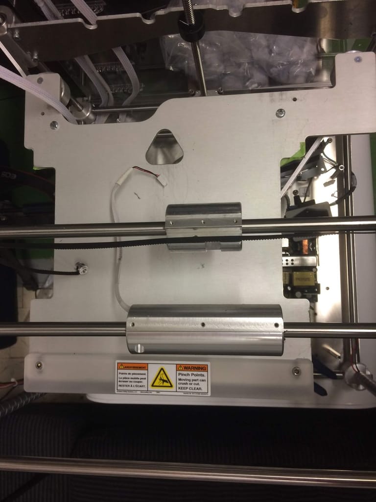
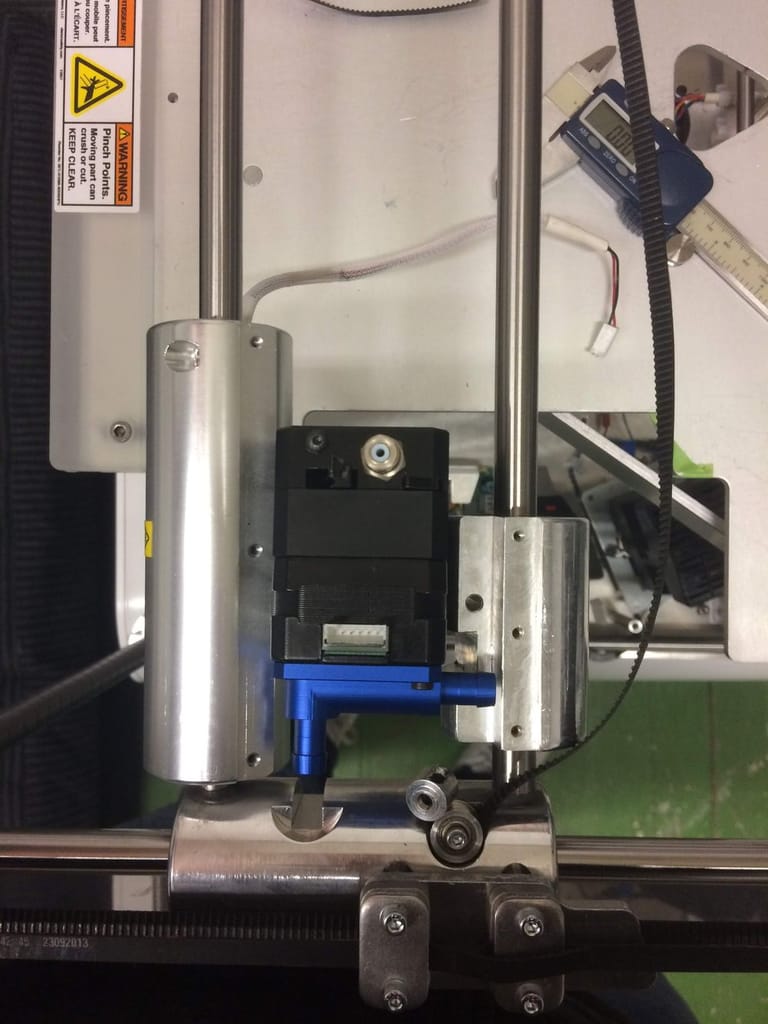
Cube without carriage
The carriage design is a step required in most 3D printer modifications. Unless someone already designed a bracket for your printer, it’s highly possible that you’ll need to make your own.
Don’t worry, this step is a lot easier than it looks and we’ll give you all the tools you need to do it.
Basic Idea
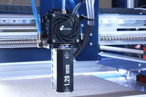
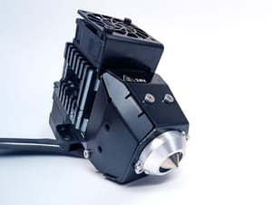
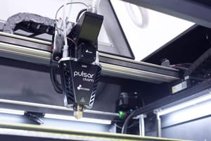
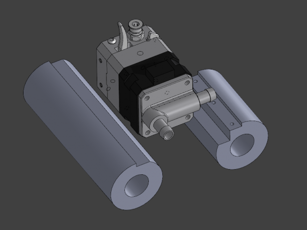
The first step is to decide how the whole extrusion system will look. Placing both the extruder and hotend is a good start, so you can figure out the mounting bracket position and how to plan your cable management. For this project, we also have to think about the liquid cooling loop. The cooling block you see are Dyze Design’s first generation blocks. They had fixed barbs, so configuration was a little more limited. The new ENP series blocks are configurable and much more flexible in term of set-up.
CAD First steps
Next step is to prepare your design files. If you’re planning on using Dyze Design products, you can download our 3D models from the support section, this will save you some time. Try to reproduce the carriage components as best as you can. Measure everything and replicate them on your CAD software.
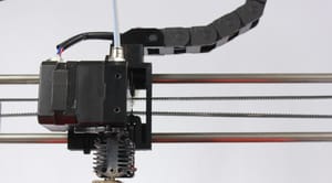
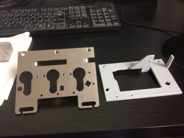
Once you have placed the carriage components and the extrusion system, you can start designing the mounting plane. Our first design didn’t include a bracket for the cable chain, but we added one on our design revision.
Once the design was working nicely as printed, we ordered it from a sheet metal supplier. The plate was made from 303 stainless steel and required 3 bends. We managed to get it for around 70$ within 5 business days. You can download the DXF, PDF and STEP file here.
Electronics
Electronics are the key to this whole conversion. There are many excellent options available, mostly known by firmware:
- Marlin firmware: Probably one of the most common firmware in the 3D printing community. It’s compatible with a ton of boards. It’s often the best solution for cost-effective printers.
- Repetier firmware: Very similar to Marlin.
- Smoothieware: Powerful, high performance.
- Revolve: Blend between an Arduino and a Raspberry Pi into an even stronger machine. Has full HD output, OS and excellent logic control.
- Duet Wifi: Powerful, easy to use, convenient.
Duet Wifi
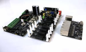
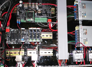
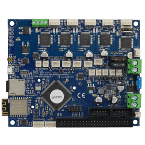
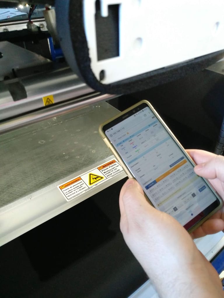
We decided to go with the DuetWifi as we had a good experience with it. This board has some major advantage over the others. First, it generates its own web interface. This is a major advantage as we can send our code and control it from any device having a web browser. We use our phone when doing calibrating routines, and our computer when slicing a part. Also, this removes the needs of having an LCD on the printer.
The Duet is very easy to configure. The whole Gcode idea is easy to work with. No need to flash the firmware.
The stepper drivers from Trinamics are getting more and more popularity. The DuetWifi use them well. We were very impressed by how smooth it moved the motors. The difference is hard to believe when comparing an Allegro A4988 or a TI DRV8825.
Power
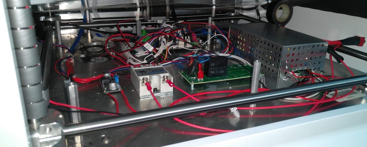
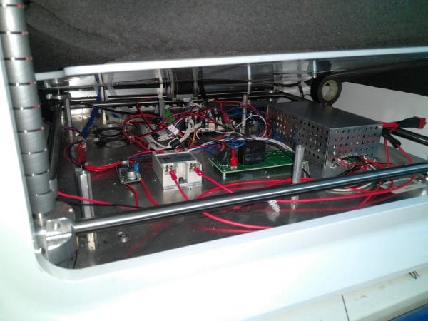
We’ll be keeping the 24V power supply (on the right, under the sheet metal box) original from the cube. The rated current is sufficient for our 24V hotend and motors.
We’ll add a step-down voltage regulator for 12V (seen on the left). The pump and some small components will need it. We used a small LM2596 based circuit as it is good and affordable. Anything equivalent will do.
We’ll also keep the relay for the environment heater (green PCB, left from the 24V PSU). Since the heating volume is big, there is no need for a PID loop. The temperature change will be very slow and a typical “Bang Bang” controller type will do a fine job with the temperature.
We’ll add an SSR controlling AC for the 300W heated bed (white box, left from relay PCB). Make sure it’s an SSR taking a DC input which controls AC output. We’ll be able to precisely control the bed temperature using this component. It’s capable of handling high current, the one we got is rated at 25 amperes. By bolting it to the aluminum base, we’ll be cooling it efficiently.
Sentinel
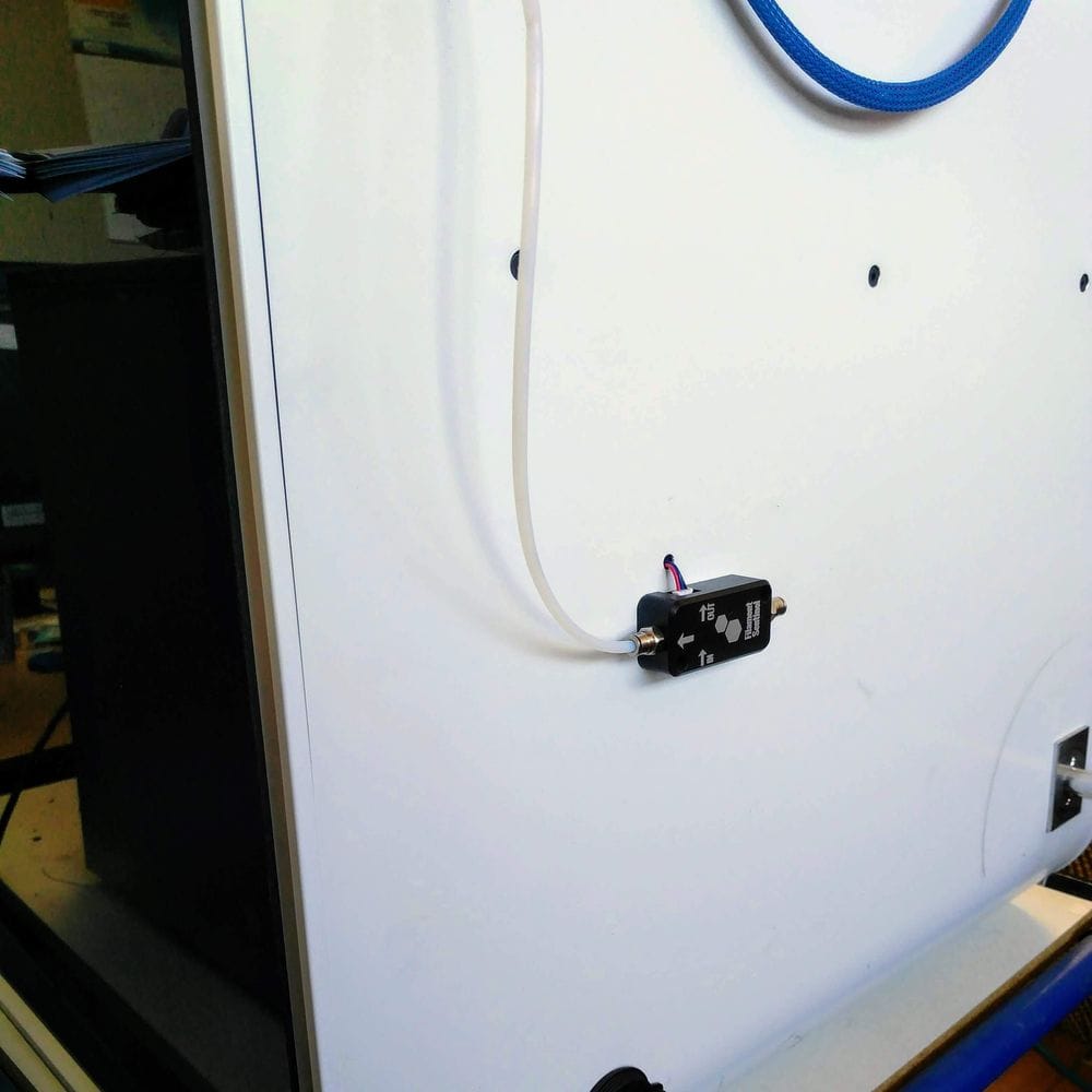
The Sentinel will be used as a filament monitor. As soon as we’ll run out of filament, the Sentinel will send a signal to pause the print. The printer will wait for the user to change the filament and resume the print.
It’s a very simple add-on and greatly appreciated in those frustrating circumstances where you imagined you had enough filament.
User Interface
As mentioned before, we have removed the proprietary LCD from the original CubePro and we didn’t replace it. Using the web-based interface from the DuetWifi is a very elegant solution that does not rely on extra hardware.
The web interface responds well to different screen size. The menu and features are well categorized and the user experience is great.
Liquid cooling
The liquid cooling system will be very important for this set-up. We’ll be keeping the extruder motor and the hotend colder than the environment. Running the environment at 70°C is a little too high for our fans. Circulating water through tubings, blocks, and a radiator does a fantastic job when the fan can’t.
Unlike popular beliefs, the water blocks and the water inside don’t add any significant weight to the system. The motor and extruder are still one of the heaviest parts from this carriage. Performance won’t suffer from this arrangement.
The parts
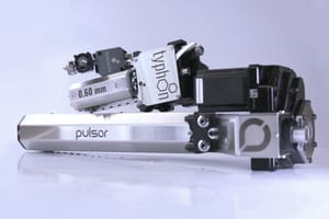
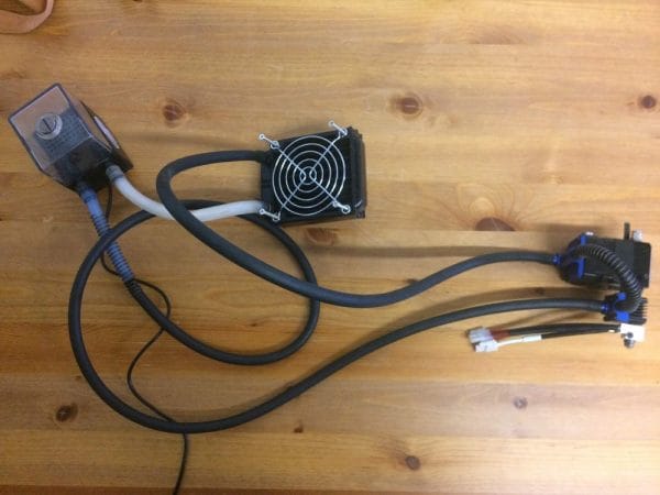
The loop is rather simple. The pump-reservoir combo pushes water through the hotend, then through the extruder motor, then through an 80mm radiator, back to the reservoir.
Pump
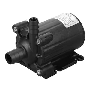
Basically, any commercially available pumps will be enough for this set-up. We suggest a minimum flow of 300 liters per hours. These tests were made using the smallest pump we were able to find, and we still have excellent cooling performance. To give you a rough idea, our hotend and extruder combo ran cooler when setting in a 100°C environment with liquid cooling compared to a 25°C environment cooled by air.
Also, since the water blocks design is different from computer waterblock, they have a very low-pressure drop. Thus it is not necessary to use a specialized pump for PC cooling for our application. Most aquarium pumps will do the job wonderfully.
Radiator
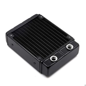
Regarding the radiator size, 80mm is not the smallest one available, but it is doing its job. A 120mm might be easier to find, and sometimes even cheaper than an 80mm. It is preferable to use an aluminum radiator, as the water blocks are made from aluminum too. This will prevent any galvanic corrosion within the system. The plating inside the blocks will help prevent any corrosion, but for a high-reliability printer, it is preferable to use the same material across the loop.
Liquid
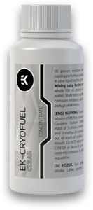
The liquid is deionized water. We added the EK CryoFuel additive mostly for biological growth inhibition and corrosion protection. Using car coolant such as “Prestone” is not suggested as the high glycol content won’t have any use since we aren’t using the printer under 0°C, will slightly reduce the heat exchange and will be more restrictive regarding tubing type.
Tubing
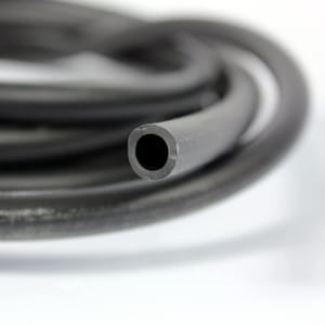
We use two types of tubes: silicone and EPDM rubber tubes. They can handle the constant flex in the system and high temperature. They are also very flexible and easy to fit with the barbs’ fittings.
Reservoir
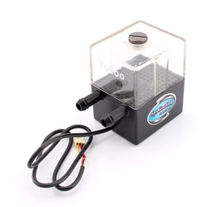
It’s always preferable to combine the reservoir with either the pump or the radiator. These are standard parts that can make it simpler for you to put everything together. A reservoir is mainly required for ensuring proper operation and maintenance. It’s possible that some bubbles trapped in the radiator find their way out after days of usage, and lower the reservoir water level.
In the next and final part of this blog series, we will explain how we installed our functional custom water cooling loop, and finally how we designed the heated bed and the controlled environment.




28 Comments
Im skipping ahead to wiring everything up. Can you please take a picture of your motor connectors as they attached to the duet? I noticed that the Y motors run in parallel, and the Z motor is bigger than the rest. What did you use for the motor current for each?
Hi Rich!
I’ll add a few pictures soon. From what I remember, we look at the motor PN and found the spec sheet, I’ll try to find it too.
The firmware settings will be shared in our next post. For the motor only, we used the following line:
M906 X1500 Y1500 Z800 E800 I30
That will help. I have xyz motors homing so far. Could you give me your M92 settings, please? I just ordered two of your extruders and hotends for integration with the cubepro. Im going to try leaving the bed unheated and print abs on pei. The stratasys uprint seems to work just find without a heated bed using an heated environment.
Hi Rich!
Printing on PEI could worth a try, definitely.
Our M92 settings goes as follow:
M92 X87.9 Y87.9 Z1066.67 E592.35
Hope it helps!
Hi Philippe,
Can you provide a schematics of the electronic connections used. We have a cube pro duo at my faculty and I want to convert it to open source with duet 3d and dyze extruders like you did.
Thank you ver much,
Cosmin
Yes, definitely! I’ll be making a new blog regarding the wiring with detailed connections. I’ll do my best to do it in a reasonable time, as you are not the first to ask for wiring instructions.
Thank you !
Hi Philippe did you ever get around to making a schematic of the wiring? I have the cube all working but the bed and chamber heater are causing my board to restart when i try to activate them.
Thanks,
Jake
Hi Jake,
Not yet, sadly. It’s still in my to-do list!
From our set-up, here is our wiring:
Duet_BedOutput+ → SSR+
Duet_BedOutput- → SSR- (Do not ground it if you are using the bed output)
Neutral → Bed
Line → Breaker → SSR_AC1
SSR_AC2 → Bed
Duet_Extruder2Output+ → Relay_Board+
Duet_Extruder2Output- → Relay_Board- (Do not ground it if you are using the extruder 2 output)
Is your configuration different than this?
Turns out the polarity of my relay board wires was the wrong way round, however the relay now clicks rapidly if I try to use the chamber heater? I do not have an SSR but I have wired an external mosfet to my 24V bed. The board keeps on resetting if i try to power the it though. Could i have an image of the wiring see if that highlights any mistake I may have made?
Thank you for your help,
Jake
Jake, I think the best would be to open a ticket so we can help you directly.
Hi Philippe, I was just wondering what settings did you used for the motor currents ? how many mA ? and also for the heater what thermistor did you used and where did you put it ?
Thanks,
Cosmin
Cosmin,
We have the following setting for current:
M906 X1500 Y1500 Z800 E800 I30
I think you have more details in part 3.
Thermistor is a 100K NTC, our “300°C thermistor”.
We threaded a M5 hole at the back and pluged it here.
Can you share what sheet metal supplier you dealt with in order to get the stainless steel plate made?
Stephen,
We have bought this part from a local supplier in Quebec (Canada):
https://www.metauxm2v.com/
There are a couple of places to check too, such as:
http://www.niteklaser.com/
https://cbrlaser.com/
Thank you
I don’t see the pump in your photo of the cooling loop. Did you use just the pump in the reservoir or the aquarium pump, too?
The pump is built in within the reservoir. Any equivalent will work.
Hello! I’m doing this same modding to the cubepro, but I am using two of your extruders and hot ends, so it is not possible to connect the relay to the extruder 2 output, as you mentioned it in a previous comment. I connected a thermistor to the THERMISTOR3 channel on the expansion port (with the 4.7k resistor and all that) and that works fine. However, the relay is not working. I have it connected like this:
3.3v -> RelayIn
RelayRtn -> HEATER3
Since the duet works as active low. Does the relay require a higher voltage? Do you have any idea what could be preventing the relay from activating?
Thank you so much for your guide.
Jairo,
To drive a relay, you need more current than the microcontroller can output.
You’ll need the proper power Mosfet to drive the relay. In that case, you should be using an SSR directly if you want to drive AC with the relay, or a proper sizes power Mosfet to drive the DC directly.
I am in the process of upgrading my cubepro. To keep is as simple as possible I am planning on using your parts list. I downloaded your carriage STEP file and sent it to a vendor to have it built. The vendor told me that the part was less then 1 inch in all directions and they would not be able to make it. Would it be possible to you to validate that the STEP file is good. If it good, I will send it to a different vendor.
Thanks
Hi Randy,
The unit of measure is mm, your supplier probable interpreted as inch.
They should scale the part by 25.4 and have the right size.
hello, where is the rest?
All the parts are published on the blog. Here’s the links:
https://dyzedesign.com/2018/11/our-cube-pro-total-conversion-part-3/
https://dyzedesign.com/2019/10/our-cube-pro-total-conversion-part-4/
I noticed in one of the comments above your posted this:
From our set-up, here is our wiring:
Duet_BedOutput+ → SSR+
Duet_BedOutput- → SSR- (Do not ground it if you are using the bed output)
Neutral → Bed
Line → Breaker → SSR_AC1
SSR_AC2 → Bed
The question I have is about the “Breaker”. What type of breaker did you use? I have a Fotek SSR-25DA already, If I need a breaker what type should should I get?
Also did you wired the AC directly off the CubePro switch or off of the line filter? The factory installed a Schaffner fn2080-12-06 line filter. I am wondering if I should wire it in front or behind the filter?
I suggest choosing a breaker rated slightly over the bed current rating. This breaker will act as a safety if there is something wrong with the heater.
We wired it directly off the switch, as there are no need of filtering AC going to a heater.
Hey, thank you for this project and tutorial.
Do you have the final part of this ?
Thanks
See you
Sure! Here they are:
https://dyzedesign.com/2018/11/our-cube-pro-total-conversion-part-3/
https://dyzedesign.com/2019/10/our-cube-pro-total-conversion-part-4/