This second part will discuss the measurable and calculable limits of the parts explained in Part I. It will be very useful if you want to find the theoretical limits of your machine.
Next part will show firmware and slicer configuration, real experiments, and prints.
Make sure you read the first part which explores the components involved in both speed and acceleration performance.
Motion
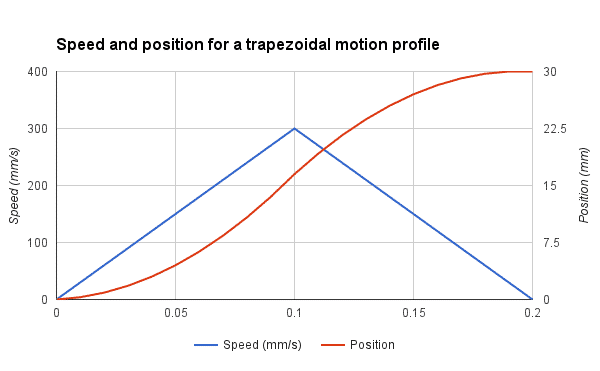
As we have previously seen the relation between speed, acceleration, and jerk, we will now explore these parameters in our goal to achieve 300 mm/s. Let’s consider our printer have an acceleration setting at 3000 mm/s^2. Remember that most printers have lower settings.
![]()
Knowing that our printer takes 0.1 second to reach its full speed isn’t very useful. However, we can find the minimum distance for maximum speed easily.
![]()
![]()
15mm is quite long for a single edge. Remember that this distance is for accelerating only. The worst case, like a square edge, will require decelerating too, so the same length will be required. In short, we need to print a 30mm square if we want to reach 300 mm/s during a fraction of a second. In this case, the average speed will be about half of the max speed, so 150mm/s .
Hotend
As you’ve seen in part 1, we have determined that the maximum output flow using a 0.40mm nozzle is about 15 mm^3/s at 250°C. The optimal line width is between 1.1 and 1.5 times the nozzle diameter, so between 0.44mm and 0.60mm. Let’s consider a line width of 0.50mm for this example. We can now determine the maximum layer height:
![]()
0.1mm layer is a good setting for printing great quality prints. We will see later if we can obtain a quality print with these settings!
Extruder
Based on the hotend maximum flow, you can determine the filament speed and your motor rotation speed.
![]()
![]()
To measure the rotation speed, it is better to use the firmware steps/mm than measuring the outer diameter of the driving wheel. The teeth penetration in the filament is important to consider. We will consider the values for the DyzeXtruder GT, and we will compare the result with the motor specs later.
![]()
![]()
Stepper motors are rated from 800 up to 5000 RPM, depending on the motor, voltage, and driver. 35 RPM is nothing to worry about.
Motors
Steppers have a unique torque-RPM curve due to the way they work. They start with a high torque which slowly decreases with speed. Depending on the parameters, some motors will be able to maintain their maximum torque for a wide range of speeds.
If we take the 0.9° stepper motor from the previous example, we can easily find the maximum RPM for maximum torque using the following formula:
![]()
![]()
133.9 RPM may sound low, but remember that it is the maximum speed at maximum torque. The maximum speed with lower torque is determined by experimentation and torque curves should be consulted.The torque is lower because the voltage applied is reduced by the back electromotive force (back EMF), thus each coil can’t reach the full magnetic force. Back EMF increases with motor rotation speed.
Extruder Motor
As you can see, the previous motor has no problem driving a 5.65:1 geared extruder for a 300 mm/s print. The actual motor inside the DyzeXtruder GT is much smaller and requires a lower current thus increasing the maximum RPM at maximum torque to 310 RPM. The specs are 1A, 200 steps and 0.0058mH. This motor can still run faster while maintaining its output torque.
Axis motor
Accelerating at 3000 mm/s^2 requires strong axis steppers. Depending on the driving mechanism, higher speed or higher torque will be required. The methodology is very simple:
- Calculate the total mass
- Find the equivalent in moment of inertia
- Determine the required torque
- Compare with motor
Belt
A general note regarding the belt is the pulley pitch diameter. It is the effective diameter where linear and angular motion are linked. We will often use the pitch radius for torque and speed calculation. For a 20 teeth GT2 2mm pitch pulley:
![]()
![]()
The length moved by a full pulley turn can be determined by the following formula:
![]()
X Axis
Belt drive is very common and very well suited for 3D printers. The belt mass is pretty negligible and the cost is low. However, the belt requires tensioning and can act as a spring and vibrate, or “ring”, especially at corners. The most common pulley size is 2mm pitch GT2 with 20 teeth.
![]()
![]()
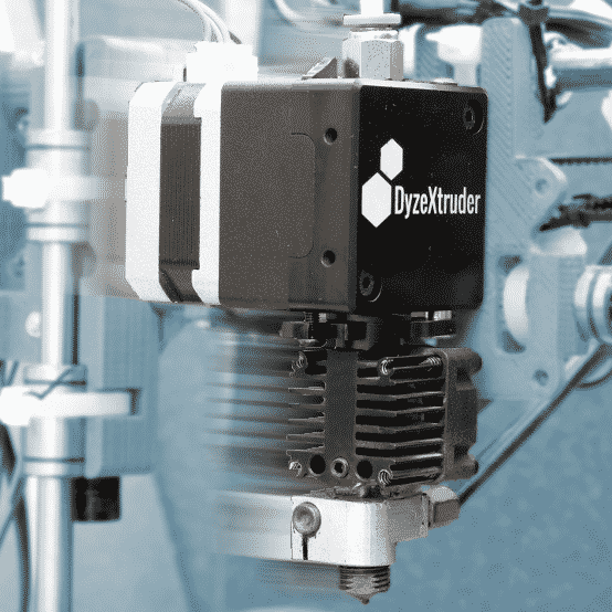
As we previously checked with two different motors, the maximum speed is currently higher than the results we had. It means simply that we cannot consider the maximum torque when the printer is running at 300 mm/s. The torque requirement will depend on acceleration and carriage mass. The extruder is often the heaviest mass to move on the X axis due to the big motor driving it. Most NEMA17 used in extruders can weight between 350 grams and 450 grams alone. The extruder with all its components can weight as much as 500 grams, which is a lot. The DyzeXtruder GT uses a custom geared reduction to lower the motor mass while maintaining a high torque output. The extruder weight only 275 grams, less than most extruder on the market.
To calculate the torque, we will first need to find the moment of inertia of our carriage. It depends on its mass and the pulley diameter. It also depends on the motor rotor inertia. Other components such as the belt, pulley and bearing have a negligible role in inertia.
![]()
If you have a DyzeXtruder GT with a DyzEnd and a printed carriage, the mass will be around 350 grams.
For a generic extruder with a powerful motor, a generic hotend and a printed carriage, the mass will be about 650 grams.
A genera NEMA17 stepper motor will have a rotor inertia of about 6.8 kg.mm^2 (68 g.cm^2)
![]()
We also need to convert our linear acceleration to angular acceleration:
![]()
![]()
Now we can calculate the acceleration torque:
![]()
As you can see on Laser 2000 NEMA17 motor, this stepper should be able to offer the required torque for our acceleration and carriage without trouble. However, with a heavier carriage as explained earlier, this motor might not be able to accelerate the carriage and would skip steps. The acceleration should be reduced, or a lighter extruder should be chosen.
Y Axis
The same methodology applies to the Y axis. for a 200mm x 200mm print bed, here are the components weight:
- Glass: 350 grams
- PCB heated bed: 125 grams
- Y axis Frame: 215 grams
- Hardware: 25 grams
- Printed part: 300 grams
For a total of 1015 grams. As you can see, this is a lot more than the X carriage total mass. You need to include a big printed part mass because you don’t want your printer to start skipping at the end.
With the same pulley and motor, we end up with an inertia of:
![]()
The required torque would then be:
![]()
The Y axis motor has a bigger load than the X axis for a moving bed. It can result in more pronounced flaws on a printed part on this axis.
Ball Screw
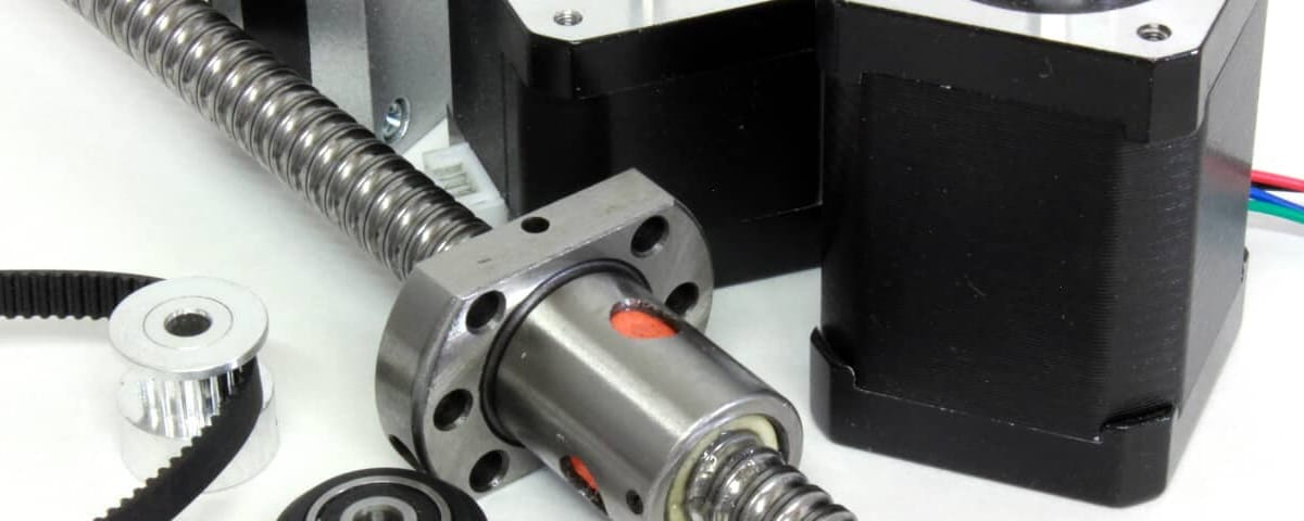
Ball screws are less common in 3D printers but more common in CNC. It has a higher mass, thus a higher inertia, and might be bottlenecking a 3D printer. Let’s see what would happen on a Y axis.
Most economic ball screws are 12mm in diameter and have a pitch of 4mm.
Since these kind of screw are very efficient, the torque required to move a mass of 1015 grams can be quite low.
![]()
![]()
The rolling balls generate very little friction and the lead pitch act as a reduction ratio compared to a belt system. For a full turn, the ball screw will rotate 4mm, compared to 40mm with a 20 teeth pulley.
The most important factor with ball screw is the inertia. This reduction ratio will require the motor to accelerate about 10 times faster than a belt system. Added the inertia of the long screw, it can generate quite a lot of torque. To accelerate to 3000 mm/s^2 as required, we can determine the rotation acceleration with the following formula:
![]()
The moment of inertia will be slightly different than before because the inertia of the screw is important compared to an aluminum pulley, we will add it to our inertia calculation.
![]()
![]()
![]()
![]()
![]()
Even if the low friction and the low advance per motor turn reduce the effective inertia for the bed, the screw has the biggest impact on inertia.
![]()
The torque required to drive a bed with a screw is more than three times higher than with a belt. However, keep in mind that the rotational speed for the pulley is about 10 times lower than with the ball screw ( 4500 RPM ). The stepper motors aren’t designed for such speed, thus the ball screw shouldn’t be able to move faster than around 100 mm/s with this set-up. A higher pitch screw could help. For small and affordable 3D printers, belts are the way to go. On larger and heavier ones, ball screw will be the best choice.
Conclusion
We’ve seen a lot of calculations on how to determine the limits of 3d printer components: HotEnd, extruder, axis motors, etc.
There are still a few limits regarding software firmware which will be covered on next part. It will cover experiments, benchmark and tests prints.




32 Comments
The density used for the ballscrew of “0.0785 g/mm^3” is much too high (by approximately 10x) so perhaps it’s a typo?
Thanks Eric for pointing that out! I have updated the calculation and the conclusion.
Hi I’m Luis from Philippines. I’m a student here and I’m planning to have a study about 3D printer. Can I ask what are some of the computations that we have to consider.
Hi Luis,
I’d be happy to help you, could you tell me more about the project and your questions?
Hi Philippe,
I’m a mechanical engineering student and I’m gonna make big 3D Printer like BigRep. I want to theoretically calculate everything in my project so while I’m searching in the web “where can I start”
I see your article and I must say that It is so helpful. I just want to ask you which other design calculations can I do for my project? What are the design calculations that cover everything for the 3D printer?
Thanks in Advance!
Best Wishes!
Hi Eshgin,
I’m so glad you like it! Thanks!
Aside from the dynamics of a 3D printer, there aren’t much to calculate. You can estimate your heater power based on your aimed heating time and temperature if you really want to calculate it. A deeper analysis could involve vibrations caused by the steppers, but this might requires FEA rather than simples calculations.
Regards,
Hi Philippe, I think that there are some errors in your calculation about the measure unit. For instance in the ball screw section, the angular acceleration that you write in 750 rad/s2 in reality I think it’s 750 rev/s2 so 4710 rad/s2. So the acceleration torque will be 0,06Nm and not 0,009Nm. The same happen in the belt section, where the angular accelration come from the angular velocity 450RPM=450/50*2*pi=47,1 rad/s and so the angular acceleration is: angularvelocity/DeltaT=47,1rad/s/0,1s=471rad/s2.
I think you are right, I’ll take a look into the calculation and correct the calculations very soon.
Just a friendly reminder that this still needs updated. 🙂
Hahaha! I really got to put this up in my To-Do list XD
Thanks for the reminder!
Just double checked and updated the post.
You were right regarding the screw, I forgot to convert the rev / s^2 to rads / s^2.
Regarding the belt, I think the formula is right, you can search “angular acceleration to tangent acceleration”, you’ll see the 2 * pi from rev /s to rads is canceled by the 2 * pi for the circumference of the belt pulley, thus the tangent acceleration is equal to r * angular acceleration.
Hi Philippe!
Where do the 742 steps/mm come from at the Extruder calculation?
Hi Richard,
This value comes from the extruder we used for the calculation. This value depends on which extruder you use.
Best regards,
Hi Maxence,
I can’t find that value in the PDF Specsheet of the DyzeXtruder GT though? Am I missing something?
Regards,
Hi Richard,
You’ll be able to find this value when looking at the support section for the DyzeXtruder GT. The step/mm will depend on your stepper driver.
Regards,
I know servos we’re not really addressed however they’re becoming the new direction of 3D printing. We are currently experimenting with 3000rpm servos (loaded rpm) and 4200rpm unloaded using 10mm pitch 12mm diameter ball screws being fairly course should produce 2x the speed of a typical 1204 ballscrew. Given most steppers have a maximum of 1000rpm that seems to be the biggest limiting factor. Will we run 300mm/s? Perhaps, but more so I have seen printers run those speeds with belts and they look like they’re falling apart with all the vibration and jerk that flexes the extrusions in some case. It can’t be long term reliable or without constant maintenance and adjustments. At least in appearance it seems so. We may consider a comparison with a gt3 sized belt however I don’t believe we will care for any higher speeds at the risk of lost steps that cannot also be controlled well due to the lack of rigidity. Using ballscrews adds a degree of complexity to design if you want A enclosed printer. Our only solution is to 1:1 belt drive on the x axis so that the servo can be kept within the housing and be able to recess into rear cavity of printer without obstruction. The y axis is not much concern in a Cartesian frame nor is the z with exception you could lose print height if frame is limited which may also require a belt to ballscrew design installing servo to the rear cavity and a fair length of belt to reach ball screw “or” rear placement of ballscrew and a deeper base to keep servo direct drive adding weight and additional frame to the printer. Various thoughts in using a z stepper and x/y servos since the z doesn’t travel as fast nor affected by the same issues a typical CNC would when using different speed/type motors. In our case we opted a z servo anyways. Partially due to our heavier hot bed assisted by 4 hiwin rails, one on each corner of bed. Mathametically I am not as witty as most nor any extensive degree, some is math, most is trial and error and understanding the essential needs in design. For me the bigger flaw in ballscrews is more so the inability to compact the design into a lightweight printer. With a 400x400x550 printable area it’s not at all considered large however I think we’re on the cusp where a belt drive will not be as accurate or reliable for the expected print quality we desire.
Totally right, servos will be used more and more. The widespread of steppers is mainly due to low cost for motors and controllers.
I’m on the same point regarding the ball screw, they are designed for high torque application. Their design isn’t made for high accelerations as the inertia and mass is very high compared to belts.
Hi
I have read this fine article many times, and tried to calculate the steps to understand it. But I am not sure that I really understand the conclusion about Accelerate Torque. Tree calculations are made in the article:
Accelerate Torque (X) = 9.889mN.m
Accelerate Torque (Y) = 22.589mN.m
Accelerate Torque (Ball screw) = 60.319mN.m
As I read the article, these numbers should be compared to the Laser 2000 NEMA 17 motor specifications. Is that the motor described in page 1, and should calculated numbers be compared with this specification – Holding torque = 300mN.m?
If so, it seems that the motor is way overrated. So for my understanding, would I be able to use a much smaller NEMA 8 with a Holding torque of 18mN.m for the x axis, but not for the y axis?
Best regards
Hi Flemming,
Yes, the acceleration torque needs to be compared with holding torque. However, holding torque will be reduced over speed. It might be able to start rotating the shaft, but will stall eventually.
Also, you need to consider a safety factor as we currently neglect a lot of details: friction, vibration, etc.
Hi! I’m fairly new to 3D printing so this might be an obvious question…under max motor RPM calculations, for the number of steps, you used 400, but should we be taking micro stepping into account here?
Thanks!
Hi Mina,
The 400 steps were considered as the motor was a 0.9° per step.
Microstepping won’t affect your maximum rotating speed, which is more related to coils and magnetization.
How did you calculate 4500 RPM for the ball screw? That seems very high
Hi Mat,
The formula goes as follow:
(300 mm/s) / (4mm/turn) * (60 seconds/minute) = 4500 RPM
However, please note that this blog was written at a time where very few screw models were existing. Now, you can easily find 10mm, 16mm and even higher pitch.
HI Phillipe, can you tell me the list of equations regarding the heating pad?
Hi Pablo!
I’m not sure what you mean by heating pad? What kind of equation are you looking for?
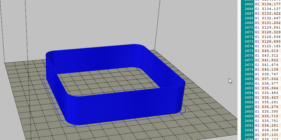
Phillipe, What was the printer used to print in the 3rd video? Looks impressive! The printer was shaking when printing at high speed. Does that affect print quality?
It’s an old RepRap style printer called the “Mix G1” from a store in Canada.
Indeed, the printer was shaking, and it’s not ideal. A printer designed for high speed printing should be light yet solid. A much different frame design and linear components should be preferred.
Hello, I Need help building a 3D printer with an H-Bot-type Gantry.X=500mmy=500mm. Loade = 2.11 Kg Max acc= 20000 mm/2s. How much holding torque do I need to achieve such high acceleration?
Hello Saianth,
We offer this blog series as a comprehensive step-by-step resource for calculating the necessary motor torque. Nevertheless, please note that we do not offer consulting services for individual user scenarios. We encourage you to make the most of the information provided in the blog.
Hey guys,
Love the guide, I think it was really well done!
Quick question/observation on the Extruder section. It looks like your RPM equation is setup incorrectly. From a dimensional analysis perspective your equation results in units of (mm^2 x steps)/(revs x minute x micro-steps).
Assuming your e-steps value of 742 is the value you determined while running at 16-bit micro-stepping then I believe the equation should be setup as follows:
RPM = [(Filament Speed)*(E-Steps)*(Gear Ratio)*60]/[(Micro-stepping)*(Motor Steps)]
This would result in units of (revs)/(min). Your calculation would then result in 489 rpm.
I would love to hear your thoughts! I very well could have missed something.
Again, this is a great guide and I appreciate the work you’ve done.
Hi Matt,
You are right, there is a mistake in the formula!
I did the math again, and ended up with something similar to your:
6.23 mm/s * 742 steps/mm * 1 turn/(200*16 steps) * 60 s/min which equals to 86.5 RPM.
I removed the gear ratio as the step/mm relation already consider the gear ratio. If you were to change the gears, the steps/mm would be affected.
If I take your result, and divide it by the gear ratio, we get the same RPM.
Thanks for pointing that out!
Good point on the gear ratio.
Thanks for the quick response!