This post is a follow-up from Part 1 regarding the general types of sensor and Part 2 regarding the detailed performance explanations.
Part 3 provides explanations regarding our choice to go with a thermistor. Also, some common mistakes are explained regarding temperature sensors.
Do not hesitate if you have any comments or suggestions that could improve this blog.
DYZE DESIGN 500°C thermistor
You might be wondering why we choose a 500°C thermistor instead of a thermocouple or an RTD.
The choice wasn’t hard when you compare each option. We wanted something that could:
- Reach high temperature
- Have a fast response
- Be cost efficient
- Be compatible with most hardware
The thermistor was our best choice.
Of course, there are not only advantages to this solution. The main drawback is the poor resolution at room temperature. The resistance is so high at 20°C that the 10 bit ADC is very close to its maximum value and has a hard time telling the difference between 20°C and 25°C. Fortunately, the resolution gets better quickly and the reading gets stable starting at 40°C. There is no risk of using this sensor at all.
To address this weakness, we worked on a firmware adjustment that would take advantage of this sensor without throwing min temp error when nothing is actually wrong. It allows a 10 to 15 seconds to preheat the hotend. The min temp is only triggered when this preheating time is done. This allows a sufficient resolution to detect if there is actually a thermistor, or if there is a problem.
PT100
The PT100 has a slower thermal response and requires an amplification circuit. It increases costs and reduces temperature stability during high-speed moves. The added amplification circuit is probably the main reason why this solution wasn’t chosen in the first place.
However, the PT100 is an excellent choice and probably the best solution for high accuracy.
Thermocouple
The thermocouple could be a good alternative since it would perform similar than a thermistor. However, it requires a similar amplification circuit than the RTD. Also, a thermocouple is very sensitive to EMI (Electromagnetic interference, mostly generated by motors). Since most RepRap machine aren’t always as protected as they should be against EMI, using a thermocouple could be quite a challenge in some cases. Also, since this sensor requires a specialized IC not available on every board, we did not choose this option.
Common mistakes about temperature sensors
My thermocouple tells a different value than my sensor in my host software
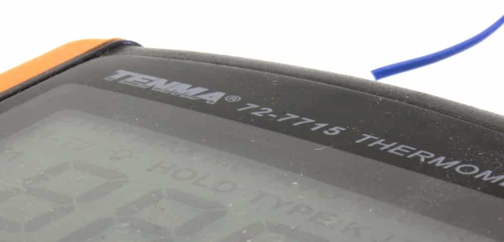
Any sensor has an accuracy rating which can greatly affect the reading. A type K thermocouple has a +- 2.2 °C or 1.1% accuracy, you need to consider the highest of the two. It means that if you read 250°C, the actual temperature might be of 247.25°C and 252.75°C.
Reading temperature means transferring heat from your sensed object to your sensor. If you use a stainless steel probe in air and you touch your heat block, you aren’t actually reading your heat block temperature. In fact, only the tip of your probe is in contact with your heat block, the rest is mostly in air at 25°C. Conduction in the probe leads to a colder temperature of your thermocouple. Therefore, it is very hard to get an accurate temperature this way.
Using a bead sensor can get closer measures, but again, there are other constraints. The pressure between the weak bead and the heat block surface affect heat transfer, and so is your (cold) fingers position on the thermocouple wire. Again, it is very hard to get an accurate reading from a bead sensor.
Unless you can immerse the sensor inside what you are trying to measure, you cannot take for granted the values you see. Remember that measuring from the outside will never give you a higher temperature than measuring from the inside. So if you are measuring a much higher temperature with your probe, it might be a sign that you have a problem.
We usually use a modified version of our heat block, heat sink or transition tube to measure the temperature properly. Jigs are holding the probes to ensure a proper and constant pressure.
My IR measures a much lower temperature than my sensor in my host software
Infrared (IR) sensors are great at measuring large surface from a long distance. The specification is usually written on the measurement apparel.
They are usually made from a lens focusing light on a sensor. This sensor is sensitive to a certain frequency spectrum of light emitted by black-body radiation. Hotends are too small for this sensor. You might get lucky to read something close to your target temperature, but do not consider it.
Can I use a resistance in parallel to improve the resolution of your high temperature thermistor?
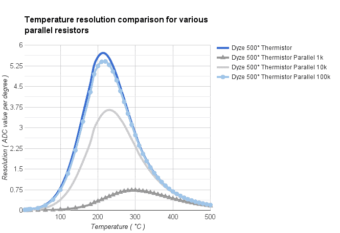
No. Having a resistance in parallel will reduce your resolution. Instead of passing through your thermistor, a certain portion of the current will pass through the parallel resistor and flatten the resolution. The graph shows a drastic reduction in resolution with every possible resistance value.
Can I use a different pull-up resistance to improve the resolution of your high temperature thermistor?
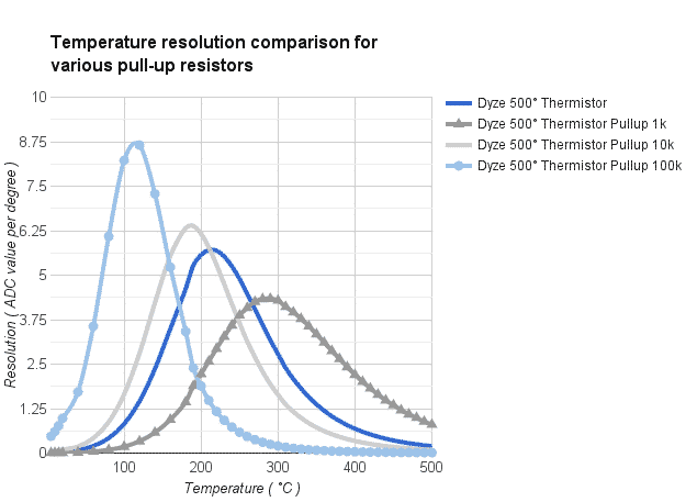
Yes, but no. Having a different pull-up resistance can increase resolution at a certain temperature, but it will decrease somewhere else. You will actually sacrifice the resolution from the high temperature to improve it at low temperature, or inversely. The resolution can have a higher peak, but it will be narrower. The graph shows a few pull-up resistances values.
The 4.7kΩ pull-up thermistor is a sweet spot for 3D printing. The resolution peak is right on printing temperature.


4 Comments
If you had spare GPIO pin on your controller board, you could switch in second resistor to improve readings at certain temperatures like this:
5V –===– GPIO –===– ADC input –=t=– ground
(resistor, resistor, thermistor)
If you set GPIO port as input, both resistor will act as connected in series. When you set GPIO as output in log.1, then only second resistor is used as pullup. Question is if anybody wants to deal with programming of this feature and if anybody would even use it.
It’s actually very clever! It could improve the low-temperature resolution problems by a lot.
Why not just use a PT1000 sensor with a 1kΩ pull-up resistor? Wouldn’t this give the best resolution at all temperature ranges because it is linear and the sensor itself has high enough resistance (1000Ω) so it isn’t as much affected by small changes. Also the ADC reading increases plenty compared to using a 4.7kΩ pull-up resistor.
And the reaction time inside a metal block is more than enough for the PID tune to keep it perfectly stable at all temperatures.
So overall the better option or am I missing any downsides except price?
A PT1000 should have an excitation current of 0.1mA or lower, otherwise it will self-heat and damage itself. By using a voltage divider like above, the current is very high if you are using 5V reference, and the sensor will be damaged.