This post will help you understand the differences and the operation of most common temperature sensors used in 3D Printing.
Each type of sensor has many key performance aspects and the goal of this topic is to compare them in details.
Part 1 will explain the most common sensor types and will take a look at the boards.
Part 2 will go in details about the performance between sensors while keeping in mind the 3D printer application.
Part 3 will provide explanations regarding our choice to go with a thermistor. Finally, some common mistakes are explained regarding temperature sensors.
Do not hesitate if you have any comments or suggestions that could improve this blog.
Sensors types used in 3D Printers
The most common sensor types are the following:
Thermistor

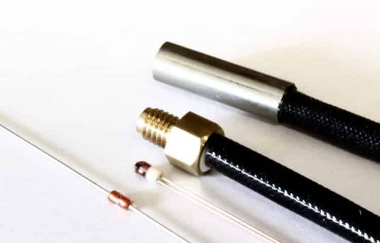
Glass thermistor
Thermistor are resistor whose resistance changes with temperature. Most commonly used type in 3D printers is NTC, standing for “Negative Temperature Coefficient”. When the temperature increase, the resistance decrease.
They are made from semiconductors, mostly silicon and germanium, and their resistance value can vary by many order of magnitude in their temperature range. A 100k NTC thermistor has a resistance of 100kΩ (100 000Ω) at room temperature (20°C) and drops as low as 100Ω at 300°C.
RTD
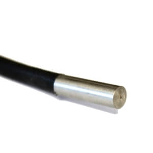
PT100 Probe
RTD are very similar to thermistors in term of operation. Rather than having a semiconductor, these are made from metals, mostly platinum, nickel or copper. RTD stands for “Resistance Temperature Detectors”. Most commonly used type in 3D printers is PT100. It has a resistance of 100Ω at 0°C.
With an RTD sensor, the resistance slowly increases with temperature. At 400°C, a PT100 will reach 250Ω. The variation is almost linear.
Thermocouple
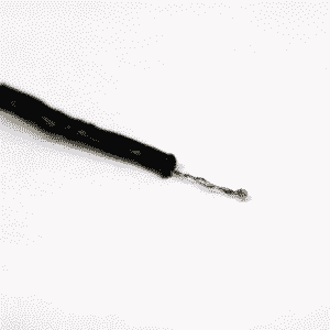
Thermocouple exposed bead
Thermocouple operates in a totally different way than the other sensors. They are made from two different metals which generate a very small voltage depending on temperature. The most common type used in 3D printers is K and is made from chromel and alumel.
The voltage increase from 0mV to 20mV from 0°C to 500°C. As with PT100, the variation is almost linear at 41 µV/°C.
Please note that the picture shows a welded bead sensor which shouldn’t be used inside a 3D printer. The actual thermocouple should be inside an electrically insulated housing to prevent any noise or ground effect. A housing can be threaded, cylindrical or flat (crimped).
3D Printers manufacturer and motherboard sensor table
Here is a list of 3D printer manufacturers with the sensor types they are using.
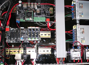
The main driving part inside a printer for sensor choice is the motherboard. Each motherboard has unique components which decide what sensor is meant to be used. The most common is the thermistor, which only requires a pull-up resistor to work.
Both RTD and thermocouple require an IC (Integrated Circuit) built for processing their respective signal. These add-on boards are compatible with most boards via I2C and SPI pins for communication, or analog pins. Some specialized boards, such as the Duet Wifi, offer specialized add-on board to enable thermocouple and RTD readings.
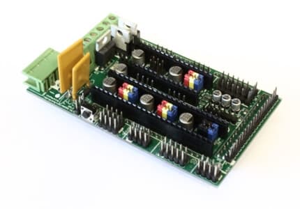
RAMPS 1.4 - 8 bits - Thermistor
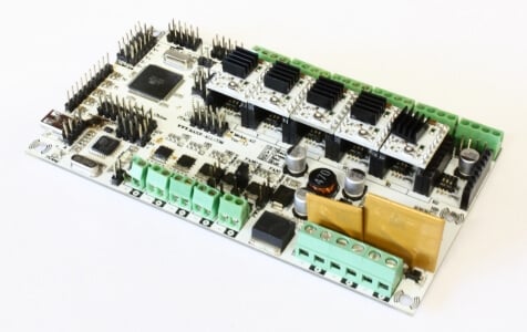
RUMBA - 8 bits - Thermistor
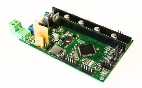
AZSMZ - 32 bits - Thermistor
| Thermistor | RTD | Thermocouple | |
|---|---|---|---|
| Printers | Prusa, Robo3D, BCN3D, Kossel, Makergear, MendelMax, LulzBot, Printrbot, Mendel90, And many more RepRap… |
Ultimaker | MakerBot, FlashForge, CTC, Wanhao Duplicator |
|
Motherboards 8 bits |
RAMPS, Rambo RUMBA, Melzi, Sanguinololu, Generation 6, Azteeg X1, Azteeg X3 | Ultimaker PCB, Ultimaker Board | MightyBoard, Azteeg X3 Pro, Megatronics |
|
Motherboards 32 bits |
Smoothieboard, AZSMZ, R2C2, Generation 7, Duet, Replicape | Alligator Board | RADDS |
Thermal sensor performance
Below is a graphical comparison for certain key aspects of temperature sensing in 3D printers. Please note that these values are based on the most common microcontroller configuration used in 3D printing, which is 8 bits microcontroller with 10 bits ADC. Having a higher resolution will improve resolution. Most 32 bits microcontroller benefit from a 12 bits ADC.
Better resolution can be obtained with specialized measurement devices, such as MAX31855, AD595, MAX6675 for thermocouple and MAX31865 for RTD, these are considered with both the RTD and thermocouple, as they are required.
The key performance aspects will be explained and detailed in part 2.
Thermistor
RTD
Thermocouple
Conclusion
Thanks for reading! This part was a short summary of thermal sensors used in 3D printer.
Follow on the next part, there will be a lot of interesting details about performance and in depth analysis!
Source
Sources
Control Engineering : Temperature tutorial
Improving the accuracy of temperature measurements


2 Comments
Nice overview, but the resolution figures you give for PT100 and thermocouple are misleading because digital interface boards for those devices are much better than that. For example, the daughter boards for the Duet WiFi/Duet Ethernet provide resolution of around 0.035C for PT100 and 0.008C for thermocouple.
The response time of a bare thermocouple in air is probably faster than that of a bare thermistor. When using encapsulated sensors in 3D printers, the response time depends mostly on the type of package. One of my RTDs is in a tiny ceramic package and responds very fast.
An interesting development is the use of PT1000 sensors connected to a thermistor input, which is now supported by some electronics and firmwares. Accuracy and resolution are highly dependent on the electronics.
This is totally right David. I think this blog could benefit from having a small update.