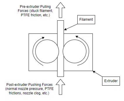
Working in the 3D printing domain, we often hear stories of people having extrusion issues. The best known issues are nozzle clogging and extruder slipping. A well-working extruder can slip when pushing forces are too high in the hotend of the extruder (printing at high speed can be a cause) or when pulling forces are too strong (for example, when the filament gets stuck). Following this reasoning, it seemed reasonable to think that restrictions in the PTFE tubing might cause extrusion problems or, in the very least, losses in the extrusion process.
The goal of the present study was hence to determine if the PTFE tubing restrictions are severe enough to cause issues and find which factors influence the most. We initially believed that length of the PTFE path, total bend angle and the bend radiuses of the PTFE would greatly affect the friction forces in the tubing, to the point where the extruder would lose efficiency.
What we found? Surprisingly, these factors do not seem to impact efficiency that much… Until they strongly do! Let us explain our process.
Test 1— Efficiency VS. PTFE Restrictions
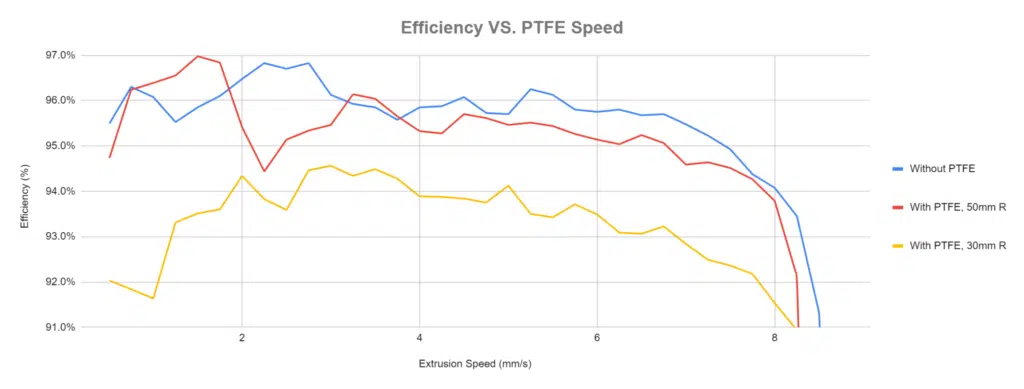
Our first objective was to verify if the whole process really had a reason to be, i.e., if the PTFE tubing restrictions did indeed cause losses of efficiency in the extrusion process. To test that, a highly inefficient PTFE path was installed on a 3D printer-like structure and connected to our extruder efficiency bench. The filament path consisted of a 3 m long, 2 mm ID x 4 mm OD tube, with various bends with angles totalling 720 degrees and constant bend radii. We then passed a filament in the circuit and extruded it. The bench measured inputted extrusion speed versus actual extrusion speed at various incremental speeds to obtain a curve of efficiency versus printing speed. We did a first test without any PTFE tubing, then with bend radii of 50 mm, then 30 mm bend radii and finally with 10 mm bend radii.
The tests resulted in the following chart:
Some major observations:
1.1— The curves seem more unstable in the beginning of the test, at low extrusion speeds.
1.2— All of the extrusion tests fail at around the same point (8.5 mm/s).
1.3— The test with the 50 mm bend radii shows a reduction of efficiency of about 0.5%.
1.4— The test with the 30 mm bend radii shows a reduction of efficiency of about 2%.
1.5— The test with the 10 mm bend radii failed due to not being able to extrude at all. The observed failure mode was filament slippage (the driving wheels grinded the filament).
The averaging technique used in the bench is probably the cause of the variation at low speeds as fewer test points were averaged (1.1). Since the losses are so low, it seems normal to observe that the max speed stays very similar (1.2). The losses in efficiency are overall very low (1.3, 1.4) until we reach the point where the extruder can’t print (1.5). This points to an exponential effect. It would hence be interesting to see what exactly causes this effect.
Test 2—Traction Forces VS. Bend Radius
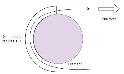
The first identifiable cause of the effect is the severity of the bend radius of the PTFE path. To test this effect, a jig with bends of various incremental bend radii ranging from 25 mm to 5 mm was printed. PTFE tubing was rolled around the bend on a 180° angle and the filament was inserted. Using a tension gauge, we slowly pulled the filament until we reached a peak in the static friction force. The tests were repeated for PLA, and PETG (we took the same spot in both filaments spools to make sure that they had the same prebend). We used a minimal amount of PTFE to reduce the effect of PTFE length.
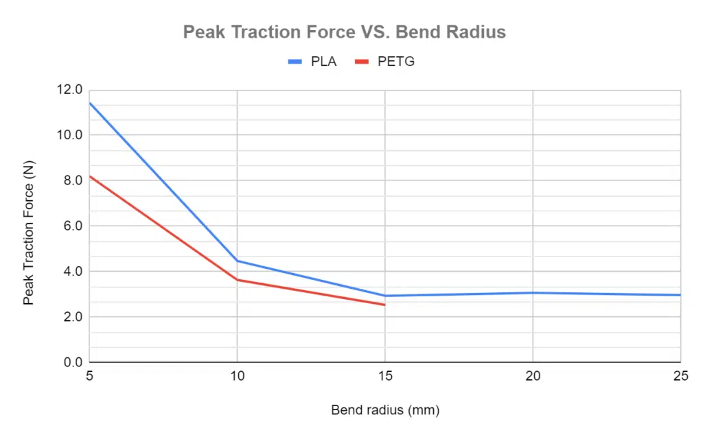
The graph obtained from the test results is shown underneath:
What we observe:
2.1— Since the gauge used can only measure forces over 2.5 N, we couldn’t obtain results for PETG at radii over 15 mm.
2.2— Traction forces were lower for the softer filament (PETG).
2.3— The traction force seems to increase exponentially with the diminution of the bend radius.
2.4— The traction force seems to stabilize at bend radii of 15 mm and over.
Sadly, it seems the tool used, although precise (resolution of 0.1 N) was not perfectly fitted for the tests (2.1). However, the PLA being the worst-case scenario as the hardest material tested (2.2) (and one of the most commonly used materials), its data is still very informative. It lets us determine that the maximum bend radius permissible on a printer appears to be 15 mm (2.4) before the traction forces become exponential (2.3).
Test 3—Traction Force VS. Total Bend
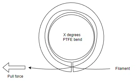
The bend angle used in the last test was 180 degrees. It would be interesting to see if the total bend angle also plays a part in the PTFE restrictions skyrocketing. For our third test, we did a similar test as testing #2, except that instead of varying the bend radius, the total bend angle was changed. This was tested using a bend radius of 15 mm and then a bend radius of 10 mm.
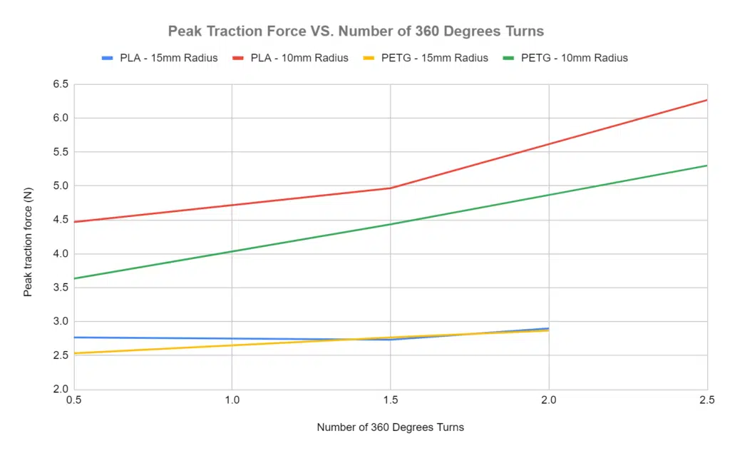
The following chart was obtained:
This is what is deduced:
3.1— The relationship between total number of twists and peak traction force seem to be quasi-linear.
3.2— The slope is steeper for a 10 mm bend radius than for a 15 mm bend radius.
The slope doesn’t reach any exponential point. It is safe to say that while the total number of twists does have an effect (3.1), it is not a critical factor at 15 mm bend radii and higher (3.2).
Test 4—Traction Force VS. PTFE Length
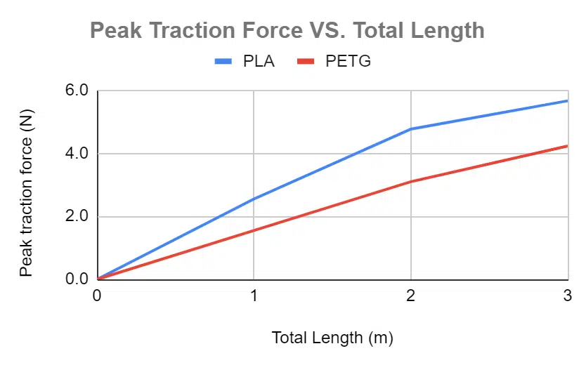
The last main factor to test is the PTFE tube length. For this testing, we did a similar traction test, but this time no bends were introduced. Only the tube length was varied from 0 to 3 m.

The following graph was produced:
We can observe that:
4.1— The curves are relatively linear.
It seems we can also eliminate the length of the PTFE tube as a possible source of the exponential traction force causing print failure as the curve is quasi-linear and doesn’t exceed 6 N, which is very low.
General
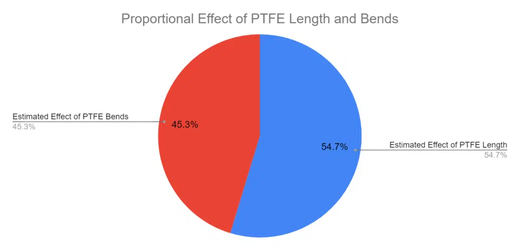
If we were to theorize an average 3D printer having 1.5 m of PTFE tubing and about 360 degrees of total bend with 15 mm bend radii, using our previous graphs, the PTFE tubing length would cause about 55% (3.5 N) of the friction forces while the bends themselves would cause about 45% (2.9 N) of the friction forces.
While it is true that bend radii of more than 15 mm do not offer much of an improvement over 15 mm bend radii in terms of PTFE friction losses, it was observed during testing that inserting filament in small bends is significantly harder than in large bends. This is especially true for longer PTFE tubes. Also, in test 1, we noticed losses of efficiency for bends of 30 mm, while the 50 mm bends fared much better. These losses, while not themselves causing printing issues, are a good indicator that the system is under stress, which means it is under higher risks of experiencing critical failures.
Conclusion
Finally, if we were to summarize our findings:
— While it is better to minimize the total bend angle and the PTFE tube length, these factors should not cause printing failures by themselves, but rather simply increase the risk of failure related to extrusion force.
— 15 mm is the absolute minimum bend radius you should have on your 2x4mm PTFE tubing.
— It is still recommended to maximize the bend radius, even if that means increasing the length of the tubing. The bend radius, of all factors studied, is the only one capable of causing print failure by itself as well as causing filament insertion difficulties.
Of course, our study did not cover every single possible factor influencing PTFE restrictions. For example, it would be interesting to see the effect of using a 3x4mm PTFE. Would the larger clearance help with the tight bends or would it cause the PTFE tubing to buckle and kink, squeezing the filament? This is left to be explored.
Thank you everybody, I hope you have found what you were looking for in this blog.

