Table of Contents
What makes a good extruder? How does it work?
The hotend has been accused quite often about being the source of a jam or clogging issue. Most of us have forgotten that it’s only part of the problem, where the extruder has its part of the blame too. The stepper motor might be clicking at very low torque, the driving teeth might be grinding the filament, or even the idler might be deforming the filament. These are very common problems of low-end extruders, where the design was optimized for cost, not for reliability and accuracy.
We’ll dive into this blog and see how important an extruder is. You’ll understand the challenges in designing a compact, powerful and durable extruder. We’ll also take a look at how we managed to improve our design by taking a deeper look into them.
How It Works
The principle is fairly simple, a motor drives one or more traction wheels. These wheels grip into the filament, a much softer material, and ensures the torque is converted to a force towards the hotend. Each step from the motor corresponds to a length of filament, thus a volume of polymer. The 3D printer controller accurately synchronized these small bits of extruded filament with the X and Y movement.
Single, Dual and Quad Driving
Extruders can be characterized as single drive, double drive, and more recently, quad drive. This nomenclature corresponds to the amount of motorized driving wheels in contact with the filament.
Despite what people think, the dual drive is an innovation that dates. One of the first FDM machines from Stratasys, the FDM series printer, was already using a dual drive system for both extruders.
The point of having more driving wheels is to increase contact with the filament, thus improving gripping and reducing slipping. Slipping is a general term used for describing the difference between the theoretical movement dictated by the driving wheel working pitch and the actual filament movement. It can be caused by either a bad traction, but also by filament deformation. This subject will be explained in further detail later.
The extrusion efficiency is the ratio of the actual length moved over the theoretical length sent to the extruder.
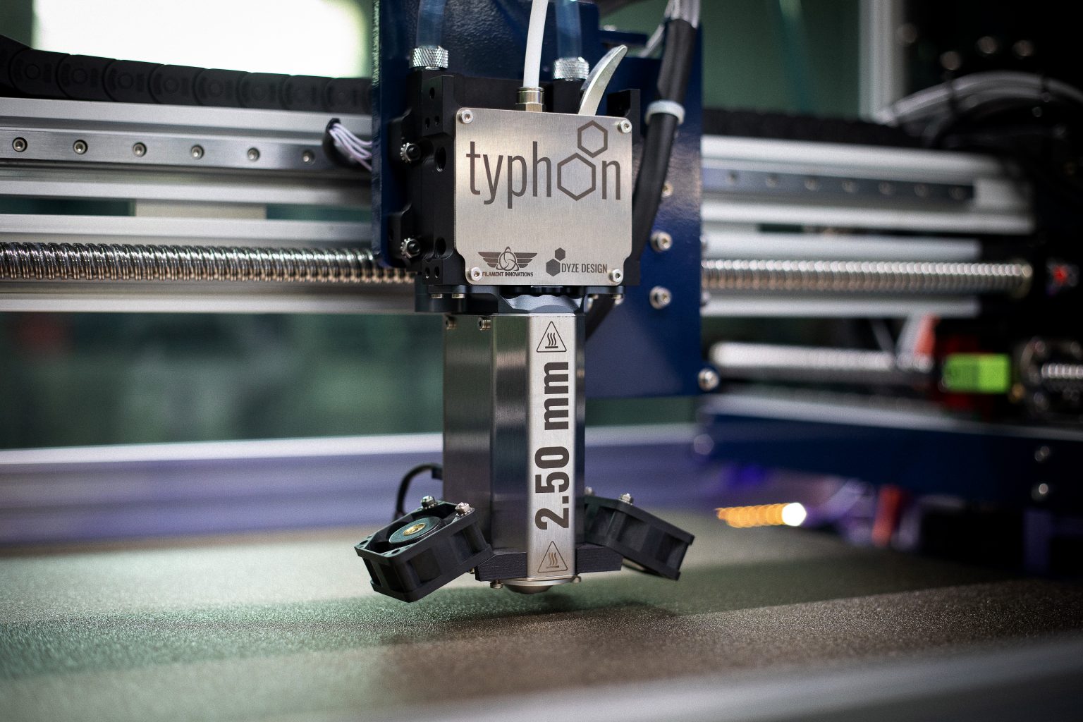
The graph below compares the extrusion efficiency between our legacy DyzeXtruder (single drive extruder), our current DyzeXtruder GT(dual drive extruder) and the Typhoon (quad drive extruder).
It can be seen that increasing the amount of traction wheels stabilize the output, meaning that you get closer to a constant volume extruded, no matter the speed. Also, having more traction wheels greatly helps reach faster speeds. As explained in our previous blog, increasing output flow will increase pressure. The driving wheels will have to push against this pressure. Without a firm grip, slipping occurs and speed can’t be reached.
Gears
Extruders will greatly benefit from using one or more gear stages. Although the X and Y axis might be moving fast, the extruder might be slowly pushing the filament. Let’s take a typical case such as below:
Printing a 0.20 mm layer height, with a 0.65 mm line width (using a 0.40 mm nozzle) at 70 mm/s corresponds to an output volume of around 9 mm3/s.
Considering a driving wheel with a pitch diameter of 9 mm, using a filament of 1.75 mm, the extruder without gears needs to spin at about 0.13 rounds per seconds ( a full round corresponds to 68 mm3).
Taking a look at the torque curve of a NEMA17 stepper motor, you can see that the 0.13 RPS is far from using the motor at its maximum potential. With this current configuration, a gear reduction up to 10 could be achieved without suffering from the stepper torque decay.

Gear will increase output torque and resolution, two excellent factors when looking for great print quality. But it’s not only a matter of gear ratio.
Gears must be reliable, precise and strong. To drive 10 kg at the filament, the gears must endure quite a high stress. Since the first DyzeXtruder GT, we supplied quality heat treated gear steel to match our high reliability expectations. No brass gears or plastic gears could pass the torture tests. Even some untreated steel gear would show wear signs.
Not only gear material is critical: both gear lubrication and environment are two other critical factors. The gears should be fully enclosed, protected from the abrasive environment dust. Dust contains pollen, textile and paper fibers, but also minerals from outdoor soil, which can be very abrasive.
Teeth Pattern
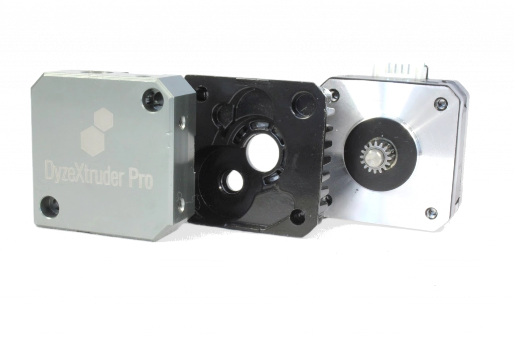
Many teeth patterns have been tested over the years. Hobbing is probably the most common type, derived from the manufacturing technique used for gears. We’ve seen knurls, standard gears with small modules, friction wheels, etc.
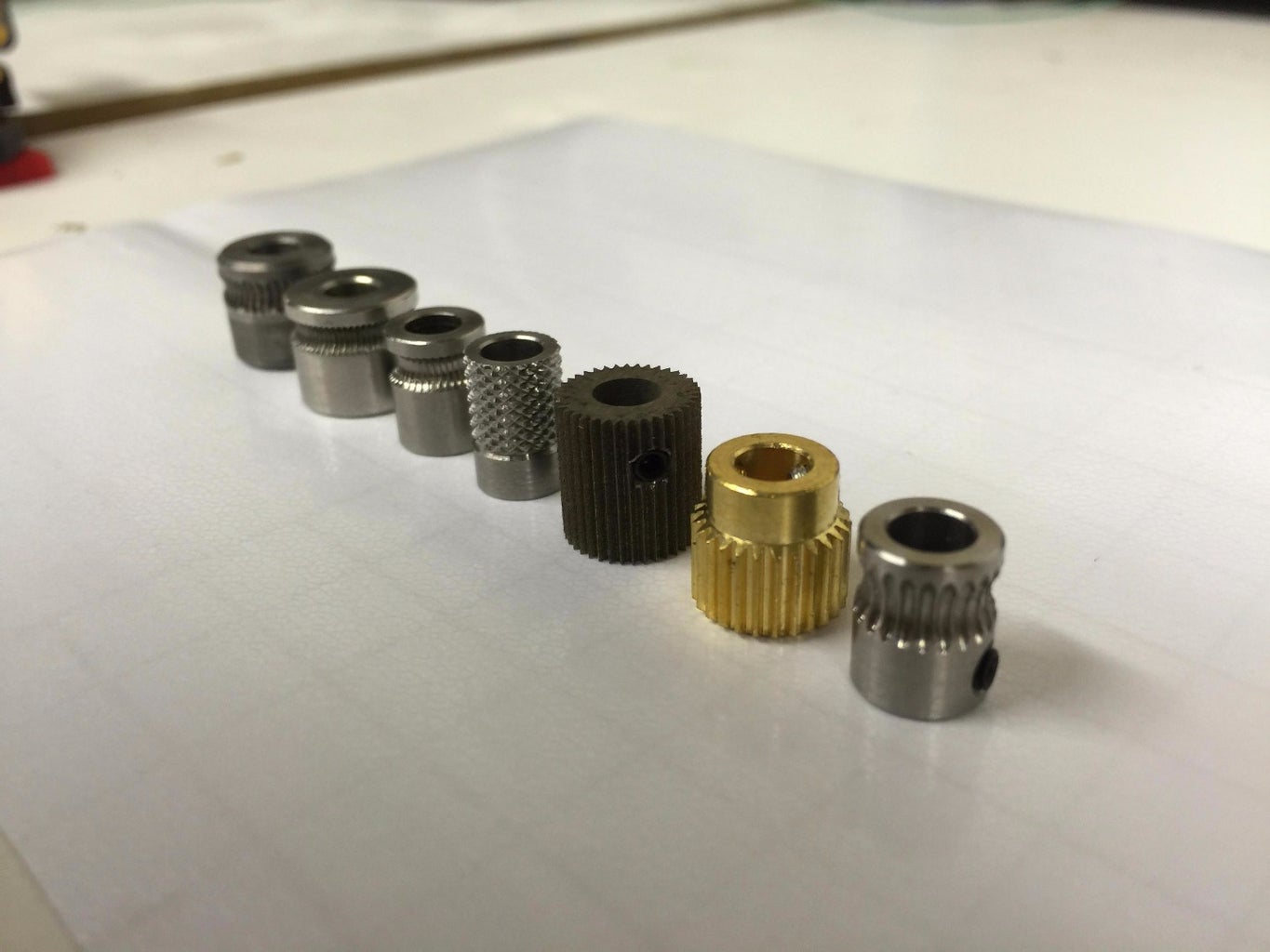
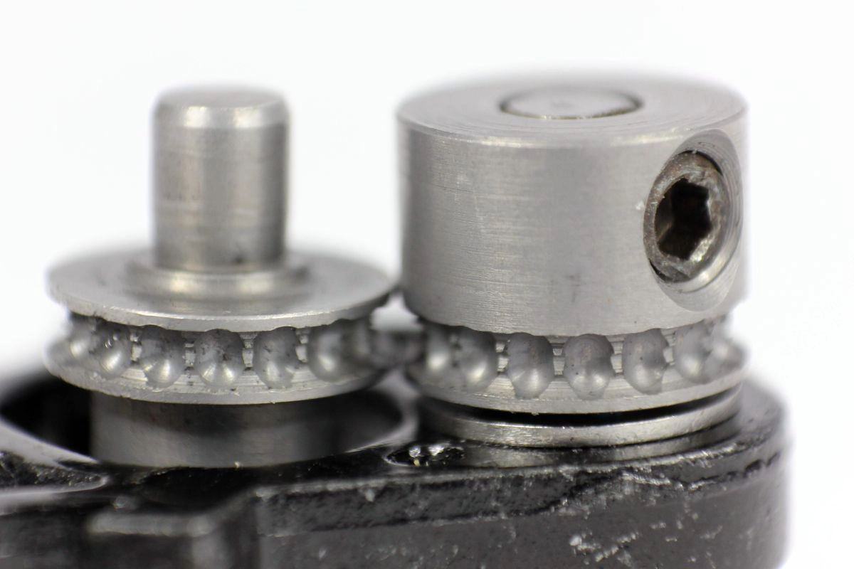
A good wheel pattern will provide enough grip to avoid shearing the filament while maintaining the filament shape. In fact, it’s quite easy to squeeze the filament as much as you can to get the best traction. However, after a few retracts, your filament will flatten and won’t fit inside you hotend anymore.
The sweet spot is a compromise between the indentation depth and the compression force. The new teeth pattern from the DyzeXtruder Pro is a good example, where the combination of groove shape and ball milled shape give a strong indentation in the filament, without changing its shape.
Wheel size
The wheel radius is quite important too, theoretically. Having a bigger radius means that there is more contact between the teeth and the filament, thus leading to better grip. However, in practical terms, increasing the radius requires higher torque and bigger components. In the world of 3D printing, we prefer having a lightweight extruder and there is a limit to the size we can fit.
Power Loss in an Extruder
Starting from the electrical power sent to the motor, you’ll realize there are many losses in the system. This is perfectly normal for an electromechanical system, but we have control over some of them and things can be optimized in a way.
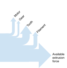
First, the power loss in the motor is caused by the Eddy current loss and winding loss. Some motors are more efficient than others, but these parameters are hard to avoid. It’s possible, however, to change motor and gear combinations to ensure the motor is working at its peak efficiency. This is one of the reasons why both the DyzeXtruder GT and DyzeXtruder Pro have a weird gear ratio of 5.65 : 1. This gear ratio is the peak efficiency at printing speed, where torque and resolution are maximized.
Then we have the gear loss, mostly caused by tooth friction, lubricant shear and bearings. The gear choice will highly affect the efficiency, where the worm gear starts with a 30% efficiency in worst cases, up to 98% with spur gear and helical gears.

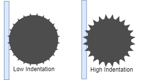
The tooth indentation is all about the teeth pattern and pressure force. If you’re trying to indent a large slice into your filament, such as with the traditional hobbed design, you’ll need high-pressure force. Those two factors together end up requiring quite some torque with rigid filament, where the indentation strength is very high.
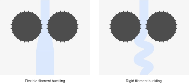
Finally, the loss in the filament after the teeth is mostly caused by the friction. Most rigid filaments won’t suffer much from friction. However, flexible filaments will highly be impacted by this factor. As the flexible material compresses and buckles, it’s effective diameter gets bigger and tries to grip the sides. This is one of the reasons why having a shorter distance between the driving gears and the melting zone is critical for flexible materials.
Troubleshooting an Extruder
Jamming used to be a very common problem, especially with PLA. The blame went all to the hotend, as the filament was stuck there (it makes sense after all). However, it wasn’t always the problem, the extruder also has its blame.
Problem Source
Too Little Torque
There are many factors that affect the torque:
- Too small motors: shorter motors tend to have less torque. However, winding can also affect both the torque and the maximum RPM.
- Low gear ratios: Up to a certain ratio (around 1:10 with a NEMA17), the extruder will benefit from having a higher reduction ratio.
- Low current: The motor will heat with over current, and will perform poorly with too little
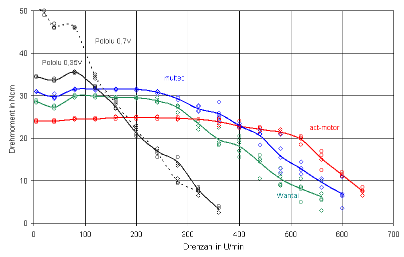
Having too little torque means that you have less margin of error during retraction and extrusion. A weaker motor won’t be able to move the filament back into position after a retraction.
Bad Grip
Another very common problem is being unable to grip to the filament. Every filament type reacts differently to tooth patterns.
- Some are harder, thus difficult to penetrate, and will tend to slowly scratch until there is a groove in the filament. Once this point is reached, the extruder won’t be able to push the filament anymore.
- Some softer filaments, such as flexible ones, will tend to avoid being gripped, and will simply avoid the driving wheel and slide over the teeth. With the Pro series extruder, we managed to see a big improvement in flexible filament extrusion with the new poke driving wheel design, and flexible filaments, once driven too hard, with start showing scales of shearing.

Filament Deformation
Based on the design, many extruders can squeeze the filament and make it flatter and larger. At some points, a bad combination of retraction amount and spring tension can lead to a filament larger than the filament path. Starting from this point, the extruder won’t be able to push the filament inside the hotend.

A bad slicer configuration can also be a part of this problem. Especially with Bowden setups, the retraction length is usually from 2 to 4 times the retraction used by direct drive users. For the same print, considering small parts are being printed with frequent retraction, the filament might be rolled over a few dozens of times with the Bowden setup, flattening the filament more each time.
The DyzeXtruder Pro has solved this issue. The new driving wheel is designed not to squeeze the filament, but rather to poke in it. No matter how much retraction, you won’t see any deformation in the filament.
Pressure Adjustment
Adjusting the spring tension has been quite a requested feature. There are many reasons why we decided not to include this in our extrusion systems. The key is repeatability:
- Precision: It’s very hard to adjust the spring twice at the same tension. Most of the time, the spring used is tiny, and only a preload difference of half-millimeter can make a huge difference on the filament. Also, most systems don’t have any precision scale. Sometimes, the spring mechanism isn’t visible at all.
- Force and Torque: Changing the spring tension will change a lot of factors such as teeth indentation and total friction. The first element will reduce the risk of grinding the filament while the other will reduce the maximum output force.
- Error: After benchmarking a lot of filaments, you ended up with a different setting for each of them. It means that each time you change filament, you need to adjust another variable, leading to more errors like setting it wrong, or forgetting about it.
- Lever adjustment: Some high-tension settings compress the spring where the lever is unusable. To remove the filament, you need to undo your spring tension, move the lever, then readjust the spring tension.
- Extrusion: The spring tension will have a direct effect on the output flow. If you’re aiming for precision with your 3D printed parts, you need to make sure not to change the spring between two prints. This is impossible if you need to clear the lever by changing the spring tension.
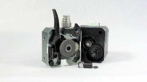
As you can see, there are more downsides of adjusting the spring tension, and these are the reasons why we decided to opt for a better designed fixed spring.
Overheating
Another common problem is extruder overheating. This is one of the simplest problems to fix: reduce the current.
Each motor slot is precisely wound at an exact number of turns, using a precise copper magnet wire. Every motor runs many different tests at the factory for phase resistance and inductance. It’s very unlikely that the motor is overheating by being out of specs.
The main causes of error are:
- Poor stepper driver design: We’ve seen a lot of variations, and some very poor copies. Some stepper drives have the potentiometer wired wrong, making the adjustment in reverse. Others won’t provide a measuring point for voltage measurements. Some will have the wrong shunt (sense) resistors, making the current formula invalid.
- Poor measuring technique / tool : Sometimes, the wrong voltage is measured. You should always use the data sheet for validation. Using an improper tool will lead to results that are off. Make sure you use a measuring device with enough accuracy for small voltage.
Calibration
Calibration is underrated. Every polymer has a different rheology and will lead to different results. Depending on the slicer and the level of precision required, there might be better options.
For example, some slicers allow users to enter a percentage as flow adjustment, without any decimals. So only an adjustment with steps of 1% is possible. Sometimes with high flow rates, it can be bottlenecking.

Filament Length Technique
The most common calibration technique involves the following steps:
- Preheat the hotend
- Mark the filament with a pen
- Note the distance between the mark and a reference point
- Extrude a known distance (usually around 100 mm)
- Measure the new distance between the mark and a reference point
- Calculate the new steps per millimeter
This technique is very straightforward, but has some limitations:
- The hotend has been hot for probably quite a while, thus it doesn’t represent a steady printing situation. Having a “pre-molten” mass of polymer will make the first 20 mm easier to extrude than the rest, thus reducing the pressure at start.
- It’s very hard to measure the exact position of a drawn line of a filament. Using a ruler and a sharpie can easily lead to an error of +- 1 mm. It might not seem like a lot, but if you’re extruding only 100 mm, you have a 2% error right there.
- It’s very hard to choose the right extrusion speed. Should you set-it at 1 mm/s and wait about 2 minutes? Or 5 mm/s and wait less. Actually, each extrusion speed corresponds to a volumetric flow rate, thus different pressure level. If you’re setting it too fast, you’ll be calibrating with too much slipping. The resulting calibration will usually overflow by using slower extrusion speed.
- It’s impossible to use this technique with pellets.
Single Wall Thickness Technique
This technique is also very straightforward, but has many advantages over the previous technique.
Here are the steps:
- Slice a small cube without infill (only one perimeter and no solid infill). Use the same speed as your normal print settings
- Small printers we usually print a 50 mm x 50 mm x 10 mm
- Medium printers with the Typhoon, we usually print 150 mm x 150 mm x 20 mm
- Large printers with the Pulsar, we usually print 250 mm x 250 mm x 30 mm
- Use a micrometer and measure the thickness of the wall, closer from the top. A vernier caliper will do, but is less precise.
- Calculate the new steps per millimeter
As mentioned before, here are the advantages:
- No variation caused by the idle time, bed temperature and other factors, since we measure the thickness of the last layers.
- Very precise measurements, based on your available tools, a digital micrometer can easily be found with a resolution of 1 µm.
- The speed is actually what you will use with a real print. There is no margin of error from this measurement to the actual print.
- This test works with both filament and pellets.
Structure and Ergonomics
The structure of your extruder is also very important. Many factors will be affected: total weight, rigidity, service temperature, etc. Let’s take a look at what should be carefully analyzed when choosing an extruder.
Materials
The housing material is critical. All the compressive loads used to pinch the filament are transferred from the bearings to the housing. Even though a plastic housing can be more affordable, you’re still pushing quite hard against the bearings to pinch the filament. With a heated environment, the plastic housing will get softer and won’t be of any use.
The driving wheel material is also critical. Especially with filled filaments such as glass fibers and carbon fibers, each tooth will be in friction with this abrasive material. Choosing the right material is important, otherwise wear can happen pretty quickly.
Latch
If you’re an experienced user, you know that you’ll be changing materials and filaments quite often. Some basic extruders don’t have any latch, others have one but you need to loosen the spring or even worse released in order to use it. To get the most out of a latch, we’re the only one to provide a “latch clip,” which holds the latch for you while you change filaments. It’s one of the most loved features from our users.
Groove Mount
Another vital feature you need to check is how to mount and remove the hotend. It’s highly possible that you’ll want to change the nozzle, clean the block, or adjust something. Some extruders are very impractical, and you need to remove the front housing (holding the gears and bearings) to remove the hotend. This is very impractical. Again, we did our best to make your life easier. A single screw can be loosened to remove the hotend, and not a single part needs to be removed. The biggest advantage is that the hotend can be removed along the filament axis. If you have a dry filament and it broke inside the extruder, you don’t need to worry; just pull out the hotend and the filament will follow.
Conclusion
I hope you liked this blog! We’ve seen how the extruder works, what’s inside, and what common problems people are having. Hopefully, it will be useful for you on your next upgrade or build.

