In this third and final part, we’ll be working on the heat bed, the controlled environment and finally the configuration for our Duet.
Heated bed
The heated bed was quite a challenge. The original “Print Pad” design is simply a glass plate with a 3mm plastic sheet glued over it. It works well with PLA, but anything else is very hard to stick. Even PETG wouldn’t stick. It was crucial to add a heated bed.
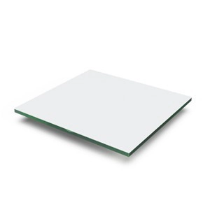
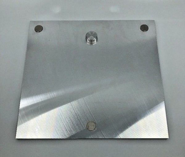
The original plate was easy to remove from the z-axis. We really liked this feature and wanted to keep it. The bottom had a big locating cylinder which seats in a triangular hole, on the Z axis system. 3 magnets secure the bed in place.
1. First test – Keep the glass bed
At first, we wanted to keep it as is. The glass plate was well designed with rounded corners and magnets. It would save us a lot of time not rebuilding the same setup.
Heating Pad
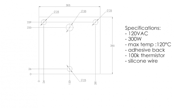
We contacted a silicon heating pad company for a customized design, hoping for a low MOQ order. We sent the following requirements at first:
After some discussion, we ended up asking for a 3 wire setup. This enables us to wire it for 240VAC and 120VAC. This 3 wire set-up separate the heating pad in 2 resistance. Wiring them in series increase the resistance and is proper for 240VAC. Wiring them in parallel reduce the resistance and is proper for 120VAC.
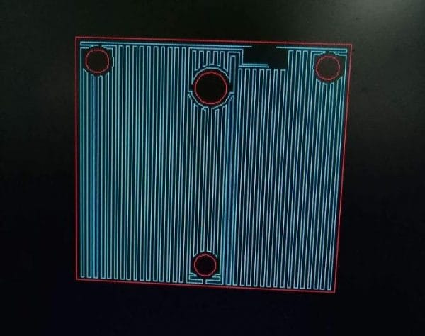
The actual resistance path looks like a sliced layer. You can see the 4 wires (two will be merged together for one wire) and an empty space for the thermistor.
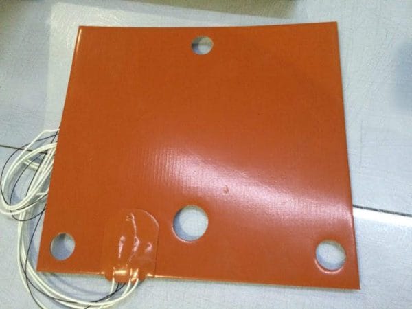
We were pleased to find a company willing to do a customized heater for a single unit at a reasonable price. They offered a great service and the heated pad was shipped quickly. They offered to make this pad available on their store, you can find it here: https://www.aliexpress.com/store/709519
Spring connector
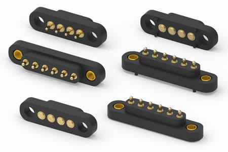
As the bed was very easy to install and remove, we wanted to keep it that way for the electrical connections too. We found Mill-Max, a company specialized in high-reliability connectors. Their spring-loaded connectors were perfect for our situation.
As we couldn’t thread in the glass, we machined an aluminum block and glued it using high-temperature epoxy.
Sadly, the epoxy wasn’t holding well. We tried to clean the surface, sand it, glue it again, and it wouldn’t stick.
The pivot movement required for removing the build plate was putting a lot of stress on the glue. We had to put the spring loaded connectors away for now and use a standard high-temperature connector.
Heating problems
We printed for a while using the original bed and it went well. But I’m sure you know what’s is going to happen once we start cranking up the heat. We had to increase the bed temperature for a high-temperature polymer in particular and something happened…
The plastic on top of the glass started warping and ungluing itself. We have reached the limit of this bed and now it is not usable anymore.
2. Second test – Use aluminum tooling plate
Unless you’ll want to stick with low bed temperature (<70°C), it is strongly advised to upgrade it too.
There are two majors choices when looking for a flatbed:
- Metals
- Glasses
Glasses are more stable than metals in therm of thermal expansion. However, they are more fragile and also worse thermal conductors.
We have decided to choose what is called an “Aluminum Tooling Plate”. It’s a cast aluminum alloy milled for flatness. There are many registered names and alloys for this material and equivalents:
- Aluminum Jig Plate
- Mold Plate
- Alca 5
- ATP-5
- MIC-6
- 100S
- Alimex 5083
These plates are easy to find and easy to work with. It can be bought from a local store and cut to size. They can be machined and drilled, which is very useful for connectors, locating pins, magnets, etc.
The ebay seller “clay-nano-systems” sells aftermarket print bed for a very good price: https://www.ebay.com/itm/332983919976
It can be an interesting solution if you don’t want the hassle of machining the plate yourself. Our heated pad will work with this plate.
With this plate and a PEI tape bought from CS Hyde, we managed to print anything with great results.
Standard connector
After the epoxy problem, we could have given a second try with the connectors, especially since they had mounting holes. However, we already had our alternative connector installed and decided to keep it there.
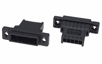
We opted for a TE Connectivity AMP Connectors Series Dynamic D-3100.
Controlled environment
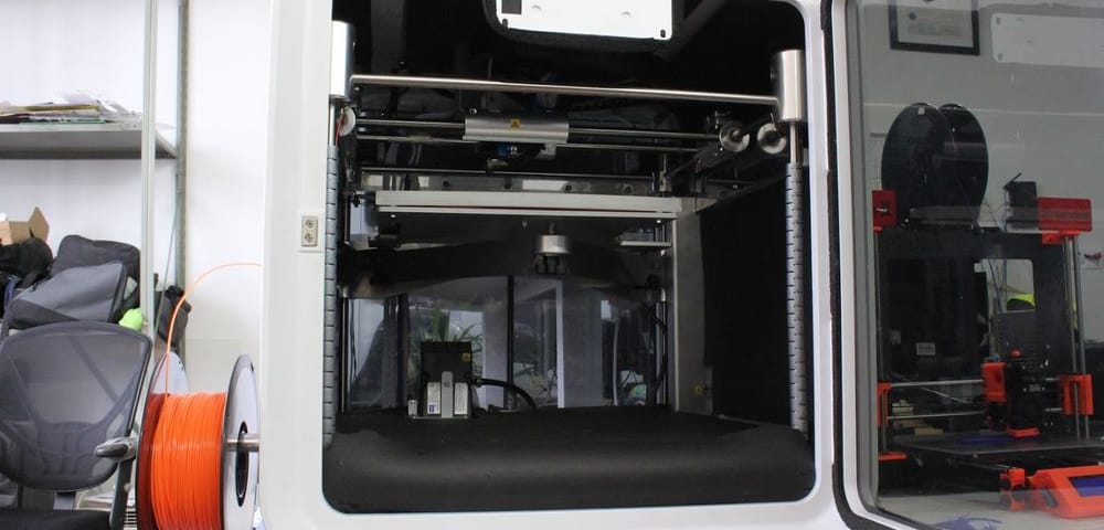
The CubePro already has a good air heater for the environment. The housing is clean and elegant for an enclosed printer. We’ll give it a nice upgrade to make it even more reliable and efficient.
Cooling the components
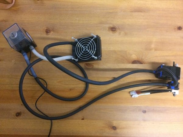
As mentioned before, the liquid cooling system will be keeping our critical components at a cooler temperature than the environment. Depending on your goal, it is not necessary to cool each axis motor.
Reaching temperatures higher than 70°C can be quite tricky as much more efforts will be required in the printer. Most cables, electronics, components will fail under higher temperature. A different printer design would be a better approach. For this printer, we’ll keep a 70°C goal.
Once you have decided which parts to cool, it is a good idea to run the loop first to ensure everything is working properly. It’s done very quickly and will save you a lot of trouble.
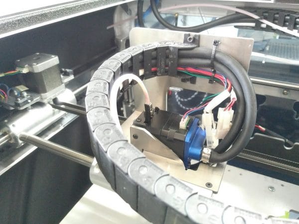
The tubes were installed inside the cable chain. There was enough space in the original cable chain for both liquid cooling tubes, plus the cables for the extrusion system.
Insulation
We added insulation to increase the efficiency of heating. Also, it helped to keep the electronic section cooler than the rest. We used Buna-N / PVC foam as the insulating material. The thickness is ½ inches. The maximum rated temperature is 105°C, which is more than enough for our application.
As installation tape, we used foam mounting tape from 3M, number 5952. It was rated for up to 120°C.
We added insulation throughout the printing zone, except for the back. This was only for preference, as the back could also benefit from additional insulation.
Configuration
You can check our configuration below for our Duet. The documentation is very well made and maintained.
Even if the Duet community doesn’t like our 500°C thermistor because it has poor resolution at room temperature ( we don’t print at room temperature ), we’ve got very nice prints quality and no trouble at all with any aspect of this printer.
; Configuration file for Duet WiFi (firmware version 1.17 to 1.19)
; executed by the firmware on start-up

; General preferences
M111 S0 ; Debugging off
G21 ; Work in millimetres
G90 ; Send absolute coordinates...
M83 ; ...but relative extruder moves
M555 P2 ; Set firmware compatibility to look like Marlin
M208 X0 Y0 Z0 S1 ; Set axis minima
M208 X280 Y295 Z190 S0 ; Set axis maxima

; Endstops
M574 X1 Y2 Z1 S0 ; Set active high endstops
M558 P0 H5 F120 T6000 ; Disable Z probe but set dive height, probe speed and travel speed
M557 X15:275 Y15:275 S20 ; Define mesh grid

;M581 T1 E0 S0 C0 ; Filament Sentinel

; Drives
M569 P0 S1 ; Drive 0 goes forwards
M569 P1 S1 ; Drive 1 goes forwards
M569 P2 S0 ; Drive 2 goes backwards
M569 P3 S0 ; Drive 3 goes backwards
M350 X16 Y16 Z16 E16 I0 ; Configure microstepping without interpolation
M92 X87.9 Y87.9 Z1066.67 E592.35 ; Set steps per mm
M566 X900 Y900 Z12 E120 ; Set maximum instantaneous speed changes (mm/min)
M203 X15000 Y15000 Z1200 E1800 ; Set maximum speeds (mm/min)
M201 X500 Y500 Z250 E250 ; Set accelerations (mm/s^2)
M906 X1500 Y1500 Z800 E800 I30 ; Set motor currents (mA) and motor idle factor in per cent
M84 S30 ; Set idle timeout

; Chamber
M141 H2 ; Assign chamber heater to heater 0
M143 H2 S100 ; Set temperature limit for heater 0 to 120C
M307 H2 A50 D60 B1 ; use bang-bang control for the chamber heater with 60 seconds dead time
M305 P2 T97968 B4630 C9.486166e-8 R4700 ; Set thermistor + ADC parameters for chamber

; Bed
M305 P0 T97968 B4630 C9.486166e-8 R4700 ; Set thermistor + ADC parameters for heater 0
M143 H0 S280 ; Set temperature limit for heater 2 to 280C

; Heater
M305 P1 T4606017 B5848 C5.548428e-8 R4700 ; Set thermistor + ADC parameters for heater 1
M307 H1 A580.4 C256.6 D6.4 S0.50
M143 H1 S480 ; Set temperature limit for heater 1 to 480C
M570 H1 P4 T25 ; Allow 25°C variation from setpoint

; Tools
M563 P0 D0 H1 ; Define tool 0
G10 P0 X0 Y0 Z0 ; Set tool 0 axis offsets
G10 P0 R0 S0 ; Set initial tool 0 active and standby temperatures to 0C

; Network
M550 PDyze Cube ; Set machine name
M552 S1 ; Enable network
M586 P0 S1 ; Enable HTTP
M586 P1 S0 ; Disable FTP
M586 P2 S0 ; Disable Telnet

; Fans
M106 P0 S0.3 I0 F500 H-1 ; Set fan 0 value, PWM signal inversion and frequency. Thermostatic control is turned off
M106 P1 S1 I0 F500 H1:2 T45 ; Set fan 1 value, PWM signal inversion and frequency. Thermostatic control is turned on
M106 P2 S1 I0 F500 H1:2 T45 ; Set fan 2 value, PWM signal inversion and frequency. Thermostatic control is turned on

; Custom settings are not configured
Leave us your comment
Thanks for reading this tri-part blog series. I really hope that we could help some of you with their printer conversion.
I’ll be happy to add any missing info. Simply leave us a comment and I’ll check for it.

