Printing at 300 mm/s is something quite impressive. You’ve probably seen it at least once on a few printer specs or on a video. Are they really printing at this speed? Maybe, but it is very hard to verify. Printing at this speed is possible but under certain conditions.
This blog will explore all the requirements to verify, understand and configure a printer so it can reach 300 mm/s or as close as possible. It might also be very useful if you are building your printer.
This first part explores the components involved in both speed and acceleration performance. It also compares the two most commons 3D printer types.
The second part will discuss the measurable and calculable limits of the parts explained in this current blog.
The third part will show firmware and slicer configuration, real experiments, benchmarks codes, and prints.
Motion basics
Before heading to hardware limits, let’s make sure we understand the basics. There are some very specific details used in 3D printing that are pretty unique, and misleading to what is seen in the industry standard, see « Jerk » below.
Speed
Speed is the easiest parameter to get, we see it in many aspects of our lives: driving ( km/h ), downloading ( kB/s ), etc. A 3D printer moving at 100 mm/s require 1 second to move 100 mm away. However, the speed does not change instantaneously, it slowly gets faster until it reaches it’s target speed. This transition is called acceleration.
Acceleration
Acceleration is a little bit harder to get. It is the change of speed in time. For example, a car start at 0 km/h and want to reach 100 km/h. It starts moving slowly and then reach 100 km/s in 10 seconds. It means that each second, the speed increased by 10 km/s, so the acceleration is 10 km/h/s. This unit can be confusing, but it is basically a length / time^2, this is the reason why you see acceleration values in mm/s^2 in 3D printers. Since the components are light and small, acceleration can be very high compared to a moving car.
Based on Marlin firmware, the standard acceleration is 3000 mm/s^2, which is a good value for a rigid setup. A 3D printer would only require 0.033 seconds to reach 100 mm/s. Some manufacturers reduce acceleration below 1000 mm/s^3 to reduce corner ringing and other imperfections.
Jerk
As mentioned above, jerk is misleading in 3D printing. In industrial motion application, jerk is the variation of acceleration, so the same logic can be applied between jerk and acceleration than we applied between acceleration and speed. Its unit can be mm/s^3.
Jerk is not used in trapezoidal acceleration profile, which is the motion profile used in 3D printers. This means the acceleration changes abruptly.
The jerk we see in 3D printing has units of mm/s. As you probably remember, these are speed units. Actually, in 3D printing, jerk is used as a threshold for minimum speed requiring acceleration. For example, a standard jerk value of 20 mm/s will make any move below 20 mm/s without acceleration. This happens often when an infill line is very short and the 3D printer will vibrate extremely quickly.
Motion profile
Motion profile is controlled by the firmware. The most common profile is trapezoidal because the logic is very easy to program. The acceleration is constant, either positive (accelerating) or negative (decelerating). Being easy to program has few disadvantages. Compared to other known motion profiles types, it reaches the lowest acceleration for the same motor power. Also, the movements can be very rough, because the jerk is considered infinite.
Advances motion profile can get smoother motion, higher acceleration, and higher velocity than trapezoidal profile, such as cycloidal and polynomial. You may want to read this great article about jerk, acceleration and motion profiles.
Hardware
Your hardware is the first limit for a high-speed printing. Specifications will help you determine the best configuration to reach 300 mm/s. You will need to make a few calculations, these will be explained in the next part.
Hotend
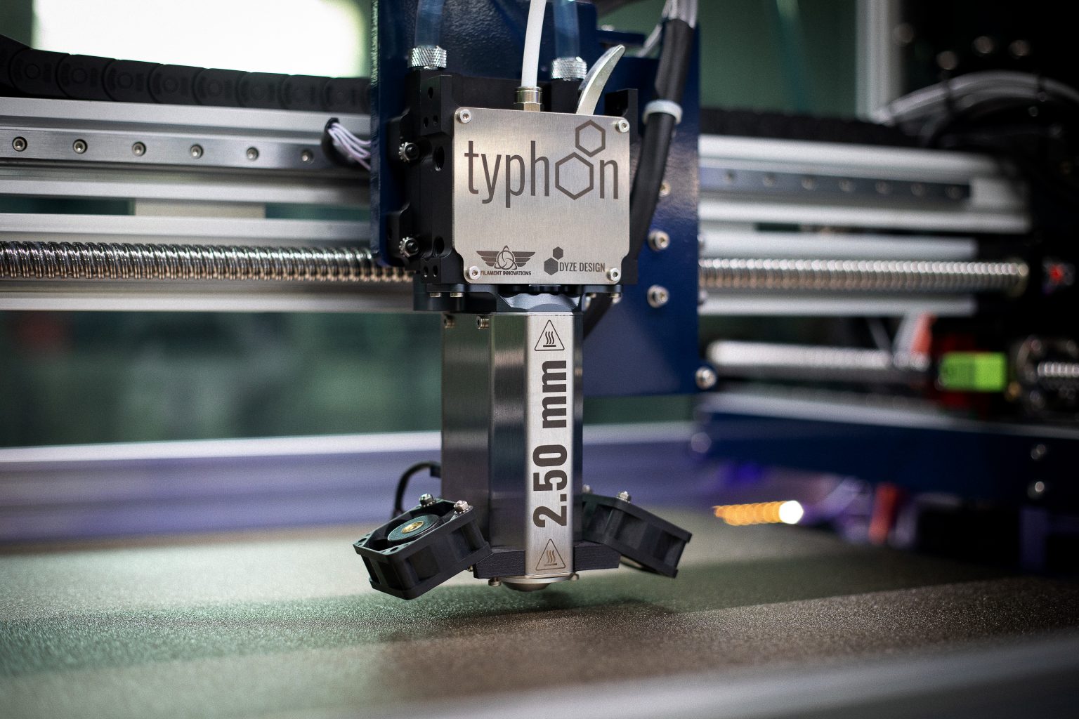
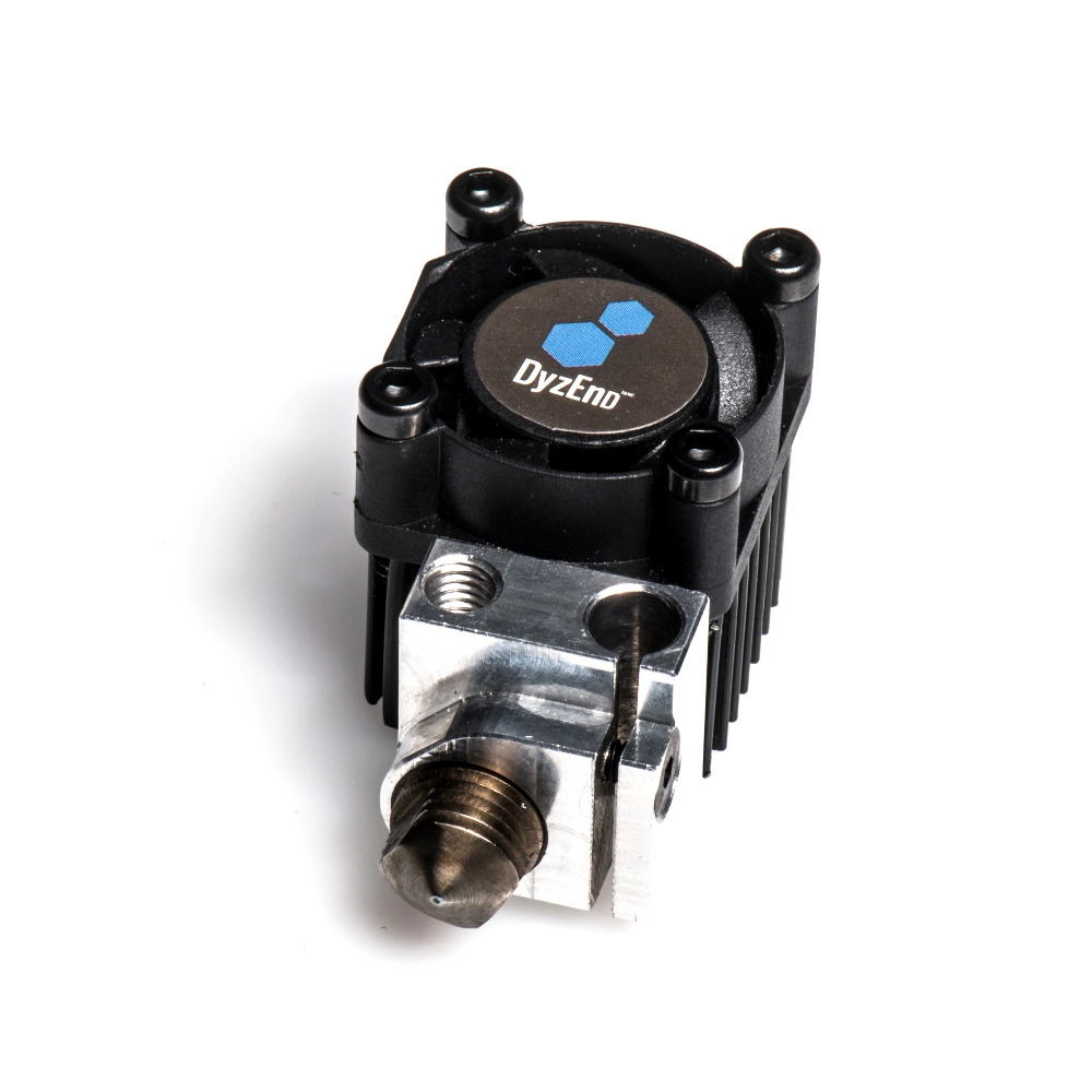
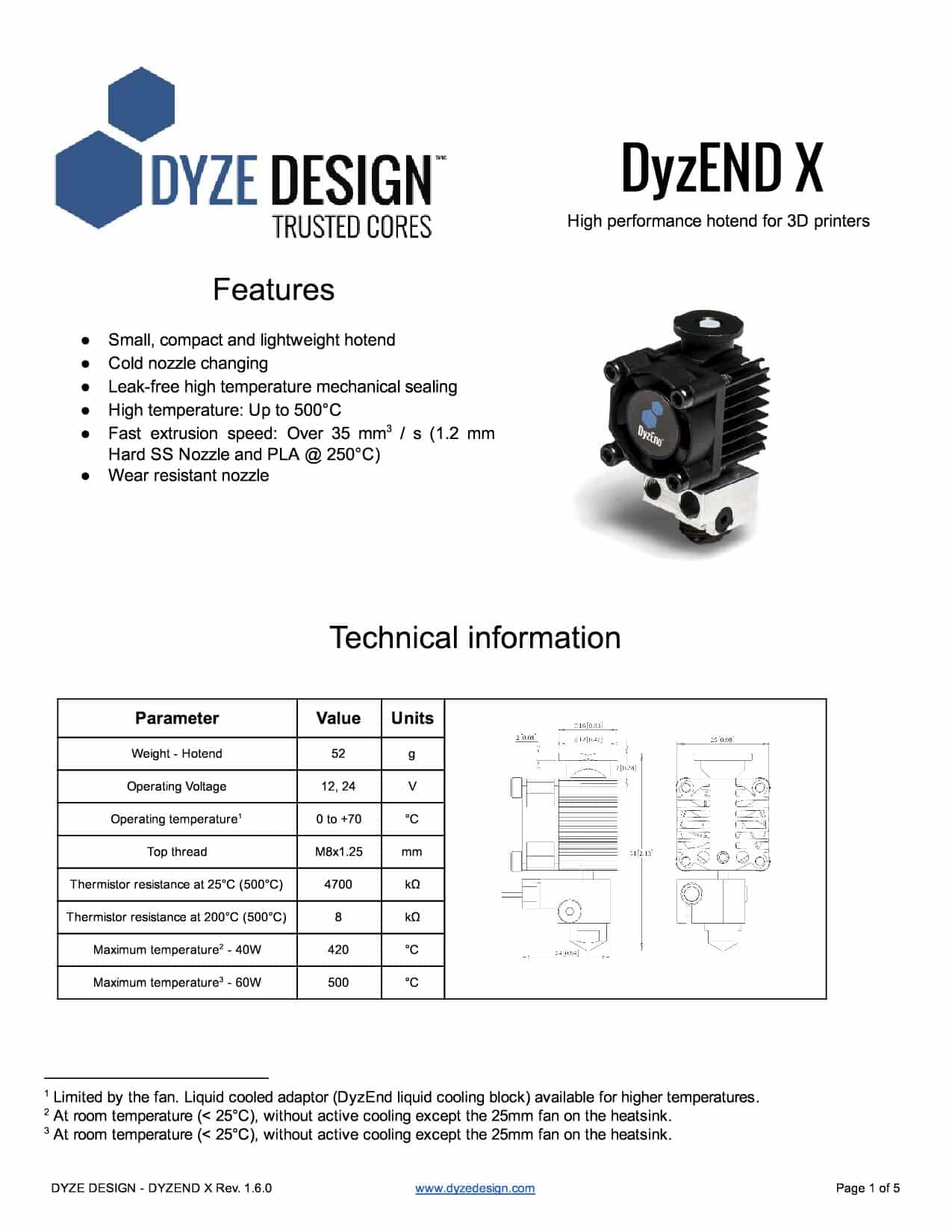
Your hotend is the first limiting hardware and most of your software configuration will depend on it.You need to find the maximum flow your hotend can handle. Sadly, not all manufacturers provide a specification sheet. Unless you are using a DyzEnd-X, you will probably need to determine your maximum flow experimentally.
Hotend spec sheet
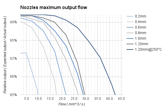
If you check your DyzEnd-X spec sheet, you will see a performance graph at the end. This graph represents the extrusion loss for a nozzle size while the extrusion speed change. This will give a start point for our 300 mm/s setup. The 0.40 nozzle line indicates that the maximum flow for a 95% actual output will be 10 mm/s of filament extruded. As you can see from the comparison, the DyzEnd-X performs very well against competition and offer a higher flow compared to other all-metal competitors.
Temperature
As you probably have seen, the graph shows values for PLA at 210°C. We won’t be printing at this temperature. In fact, even if your sensor is telling you a temperature, the molten plastic inside is probably at a different temperature. Time is required to transfer heat to your filament. By increasing speed, you reduce the time to heat your plastic, thus reducing your actual plastic printing temperature. It is very important to increase the printing temperature for fast prints. Increasing temperature will reduce the pressure required to print at a faster speed.
As you can see on the previous graph, increasing the temperature up to 250°C will increase the flow by about 50%. With our current 0.40mm setup, will be able to reach about 15 mm^3 / s.
Extruder
The extruder is also critical for high speed printing. However there isn’t many parameters to play with to get the optimal results. Its performance mostly rely on the hotend.
Construction strength
Make sure to get the most reliable solution for your budget. Higher print speed requires more output torque, a geared extruder is a better choice for optimal performance.
For long lasting reliability, all-metal construction extruder should be preferred. Heated bed, hotend, and enclosed chamber will heat the air around the extruder and greatly reduce the mechanical properties of any plastic components.
Dual pitch system reduces the risk of grinding the filament. At high speed, the high force needed to push the filament will increase the chances of slipping and grinding.
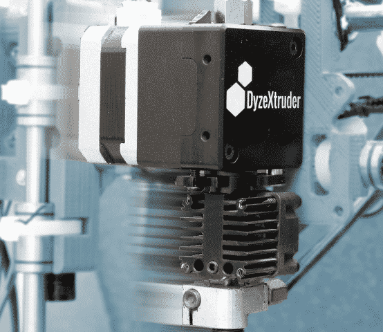
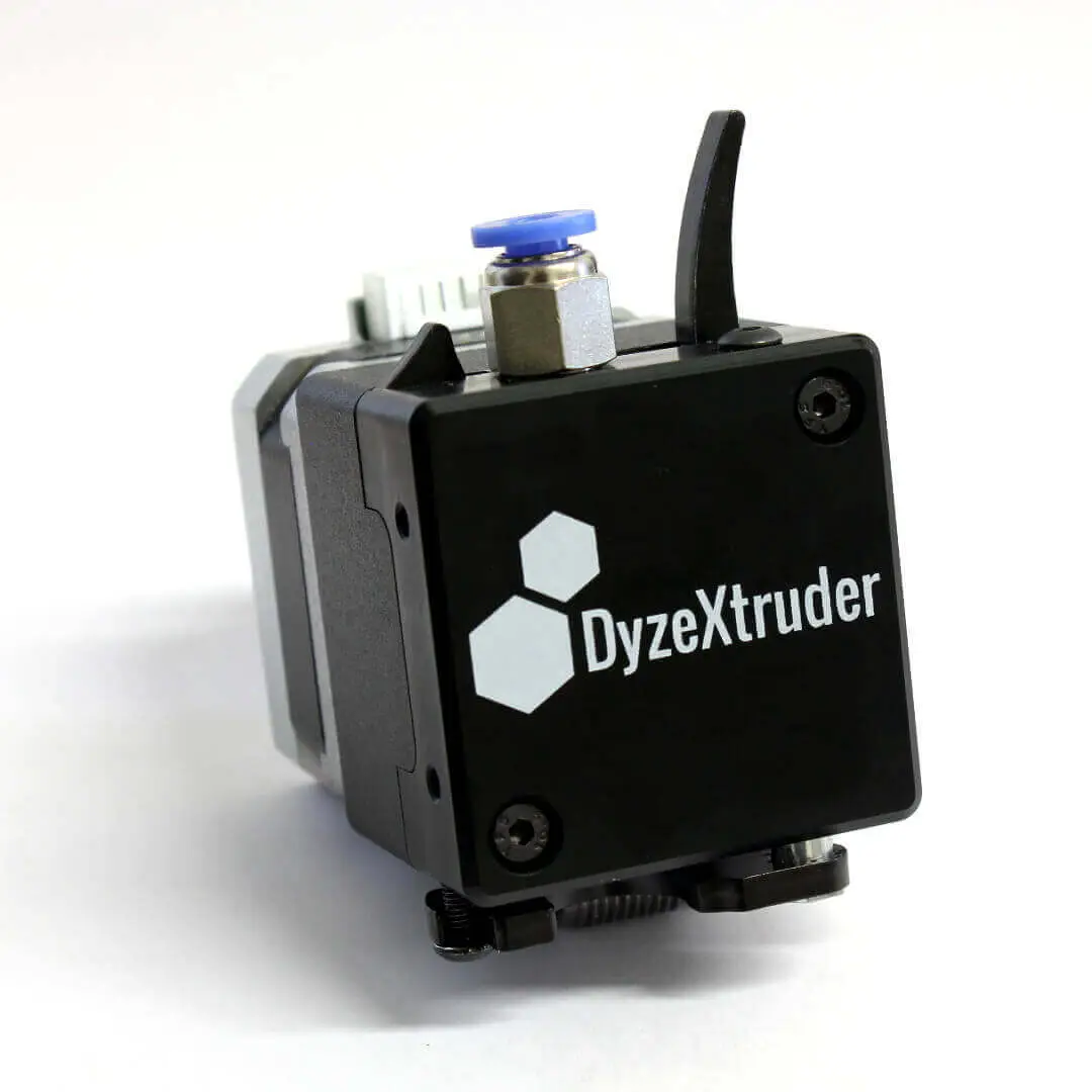
The DyzeXtruder GT is a high-performance solution for this kind of application. It has a no-compromise construction for amazing print quality, even at very high speed. Check the shop page for more information.
Optimal spring tension
There is less adjustment required with the extruder than with a hotend. If you have an adjustable spring tension, find the sweet spot where your filament does not grind and where you do not reduce your maximum motor torque due to over-tightened springs.
Maximum speed
Geared extruder greatly benefit from higher torque, but the maximum speed is decreased. For a Nema17 motor, make sure to use a motor with a ratio lower than 12:1. Higher ratios won’t be able to extrude fast enough.
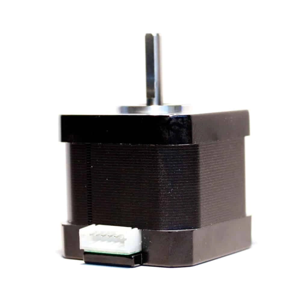
NEMA17 Stepper motor
Motors
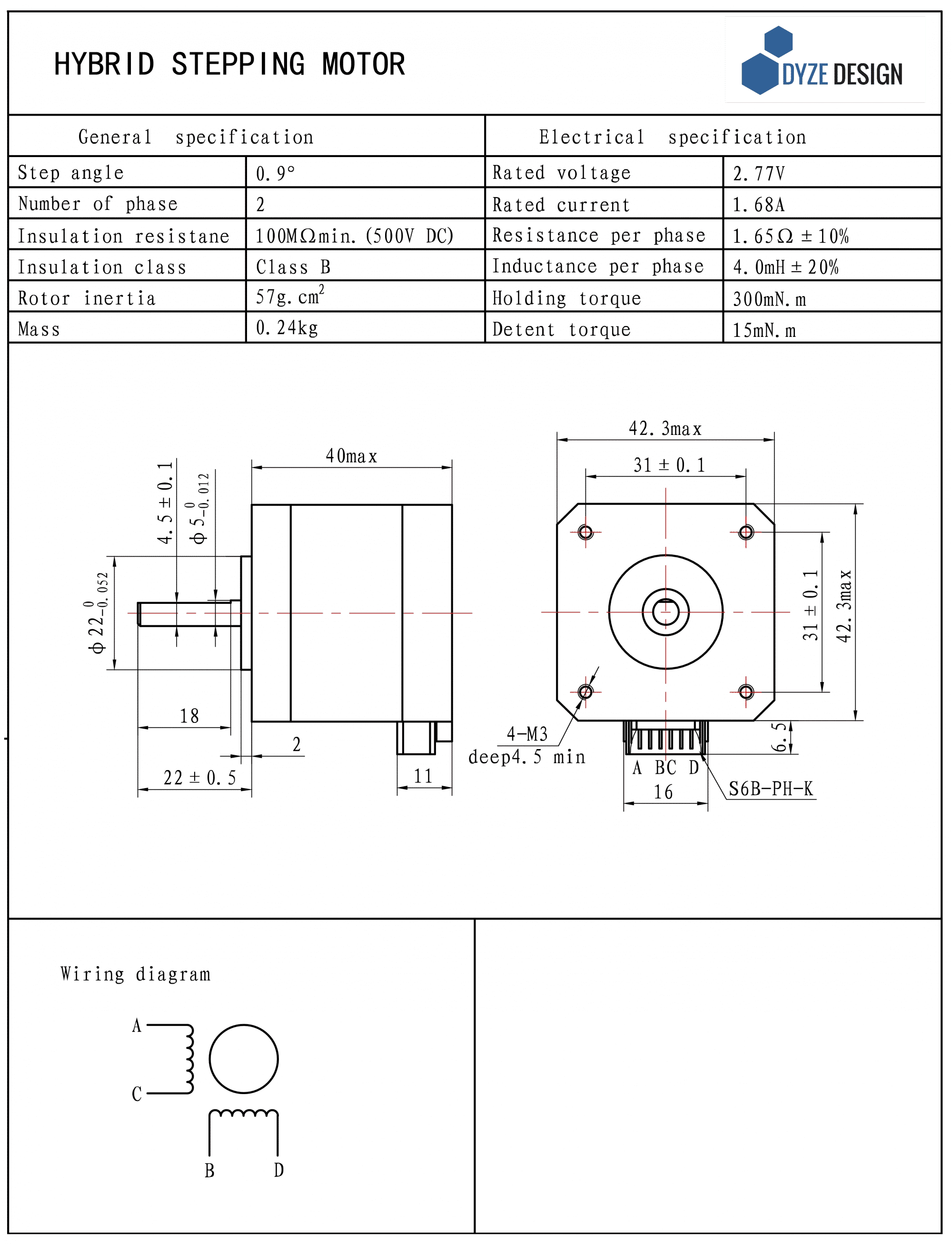
The X and Y motor will be working very hard at this speed. Some high torque motors won’t be able to reach high rotation speed, some high inertia won’t be able to reach high acceleration. We will check how to determine the maximum performance of a motor and what can be improved.
Motors specification
Your stepper motors is built to get a good compromise between torque and speed. You can have two completely different motors with the exact same physical size if you change the windings. A higher inductance stepper will lead to a higher torque, but a lower maximum speed. Since a higher inductance magnet takes longer to get activated, the maximum speed is reduced.
There are very common standards between motors manufacturers, but any variation can be customized.
A bigger motor will have more torque, but higher inertia. Inertia is linked to acceleration. The higher the inertia, the higher is the torque required for a given acceleration.
Printer
The printer is considered as the 3 axis movement system. Cartesian and delta are the two most common used in 3d printers. Their construction will greatly impact the speed and acceleration. They both have their own advantages. The major point to focus is the weight because the speed will be determined by the motors.
Cartesian vs Delta
Cartesian printers are very common, and deltas are gaining in popularity. It can be very hard to compare both motion system because there are many variations with their own advantages.
| Cartesian | Delta | |
|---|---|---|
| Pros | Easy to debug Easy to calibrate Carriage can be heavy, direct drive possible Low CPU requirement |
Fast prints High speed on each axis High acceleration Low maintenance |
| Cons | Print quality highly depends on printer robustness Low Z axis speed Low acceleration |
Carriage must be light, direct drive not possible High CPU requirement Arm vibration |
Carriage
The carriage moves the hotend and sometimes the extruder. The lighter it is, the higher the accelerations can be. The bearing should be well integrated to avoid the added mass of a bearing housing. Light material such as aluminum should be preferred with as many material removals as possible. Many great designs exist made from plastics such as the one from jonaskuehling.
Delta printers have another name for a carriage: effector. It is very rare to see an extruder mounted on it due to the high mass. The long arms aren’t made to move heavy stuff, they are better at moving light objects very quickly. It is commonly used as a picking robot.
Robustness
High acceleration means high dynamic forces. The printer must be robust enough to keep good printed part tolerances. Some printers are made to be economic and aren’t designed to handle such forces. Cubic and prism frame shape should be preferred over open frame design.
The Mendel Max is a great example of a good frame design. The number of frame parts is minimized and still, the frame is very sturdy.
Conclusion
There are many hardware parts which will affect speed and acceleration of a 3D printer: Hotend, extruder, motors and printer frame. The basic parameters have been explained and detailed.
The next blog part will cover all calculation so you can see the limits for printing at high speed.
