This post is a follow up from Part 1 regarding the general types of sensor.
Part 2 will go in details about the performance between sensors while keeping in mind the 3D printer application.
Part 3 will provide explanations regarding our choice to go with a thermistor. Finally, some common mistakes are explained regarding temperature sensors.
Do not hesitate if you have any comments or suggestions that could improve this blog.
Thermal sensor performance
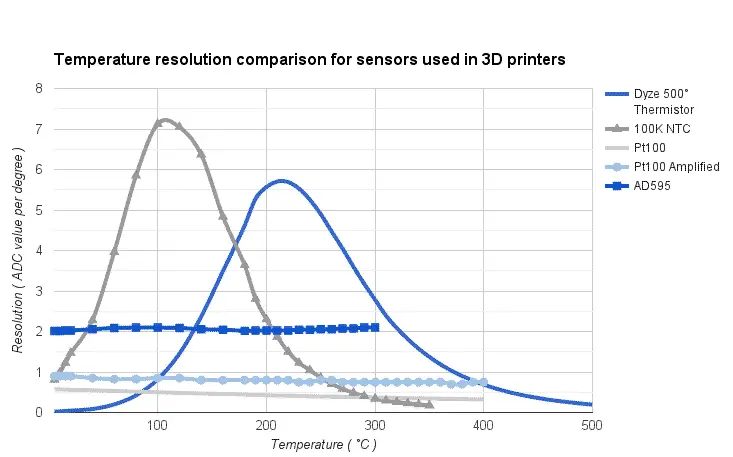
Below is a graphical comparison for certain key aspects of temperature sensing in 3D printers. Please note that these values are based on the most common microcontroller configuration used in 3D printing, which are 8 bits microcontroller with 10 bits ADC. Having a higher ADC resolution will improve sensor resolution. Most 32 bits microcontroller benefit from a 12 bits ADC.
Better resolution can be obtained with specialized measurement devices, such as MAX31855, AD595, MAX6675 for thermocouple and MAX31865 for RTD. These specialized chips will be analyzed if the following sections.
Thermistor
RTD
Thermocouple
Maximum temperature
The maximum temperature determine what is the highest temperature your sensor can be used. At higher temperature, the sensor may degrades or may be unable to output any readable signal.
A higher temperature allow the user to print more kinds of plastics. Below is a short list of engineering plastics with their printing temperature and tensile strength for reference. ABS might require a low temperature to melt, but the mechanical properties are much lower than other high temperature thermoplastics.
| Plastic | Printing Temperature (°C) | Tensile Strength, Yield (MPa) |
|---|---|---|
| ABS | 200 – 220 | 29 |
| PPSF | 330 – 350 | 55 |
| PEI (ULTEM 1010) | 330 – 350 | 64 |
| PEI (ULTEM 9085) | 330 – 350 | 47 |
| PPS (Ryton) | 316 – 343 | 85 – 190 |
| PEEK | 350 – 400 | 59 |
| Dupont VESPEL | 410 -420 | 100 – 220 |
| PAI (TORLON) | 370 – 427 | 110 – 225 |
Cost
The cost is affected by both the sensor price and the need of add-on circuits. Despite the fact that we see more and more great motherboards design, the most common ones don’t have an amplifier circuit for a PT100 or a thermocouple. Using a thermistor in 3D printing enable most users to directly fit this sensor to their motherboard, without any physical changes required.
The thermistor is probably the easiest sensor to connect with a microcontroller. Only a resistance is required to be able to read with great accuracy. This passive component can be found below 0.05USD each when bought in bulk. The thermistor can be usually found below 5.00USD.
The RTD sensors usually require an amplification circuit built from specialized components. The simplest design uses an OP-AMP. However, this design have some limitation and cannot offer a resolution as high as a specialized IC. The MAX31865 is designed with a built-in 15 bits ADC and offer a resolution as high as 0.03°C. However, the cost for this chip alone is very high and breakout boards can be found around about 30.00USD. The probe is also expensive, as is the cost of platinum. Basic probes starts at 20.00USD and can climb up very quickly depending on precision class.
The thermocouple require a specialized IC to work. The AD595 is very common in the RepRap community because it outputs a voltage and is simple to interface. The cost is about 18.00 USD. The resolution is however limited (by the microcontroller) compared to other options such as the MAX31855 which gives a resolution of 0.25°C for about 15.00USD.
Resolution
The resolution represents the smallest changes the device can see. It depends on the motherboard circuit. Almost every sensors end up in the microcontroller ADC (Analog to Digital Converter). Some IC for thermocouples have their own ADC separated from the microcontroller, thus allowing a better resolution.
An ADC has a resolution in bits. A 10 bits resolution means 2^10 (1024) values can be distinguished. When a voltage gets into the input of an ADC, it gets converted in a value between 0 and it’s maximum resolution minus 1, 1023 in this case. For example, if a 10 bit ADC has a reference voltage of 5V and receive an input voltage of 5V, it will convert it to a value of 1023 to the microcontroller. If the input voltage is 2V, it will output a value of 410 ( 2V * 1024 / 5V ).
The graph shows that both thermistor have a different resolution based on the temperature. In fact, both the 100K thermistor and our high temperature thermistor peak at very high resolutions compared to other types of sensors. Please remember that we are still in the context of 3D printers and these values represent what is inside most firmware and boards. The RTD sensor has the lowest overall sensitivity at 0.5 resolution per degree (2°C resolution). Once amplified, the resolution goes a tiny better at 0.8 resolution per degree (1.2°C resolution). The thermocouple has a sensitivity of 2 resolution per degree (0.5°C resolution).
Response time
Response time correspond to the time it takes to reach 63.2% of the actual value. For examples, if you take a PT100 sensor with a response time of 15 seconds at 0°C and plunge it it boiling water, it will read 62.5°C after 15 seconds. After 1 minute, the sensor will read 98°C.
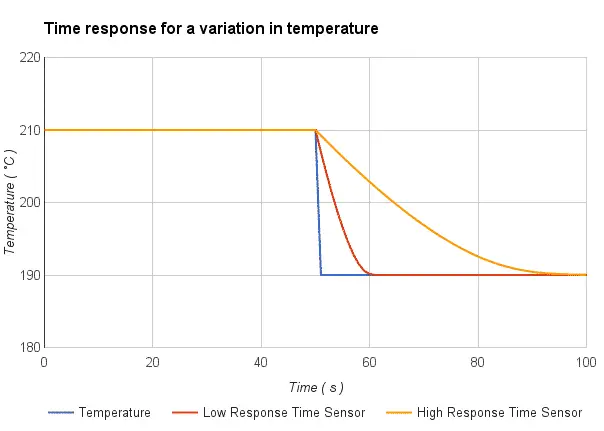
Response time correspond to the time constant of a sensor (τ). Suppliers usually specifies if the value correspond to a change in water or in air. Water is always faster than air since it transfers heat quicker. It is very important to compare two sensors on the same basis.
In many applications, a response from 10 seconds to 60 seconds is very acceptable. However, on a 3D printer, it is totally different. Since the hotend must be moved very quickly, it is constantly cooled by the environment and the entering plastic. Having a longer thermal response could make a hotend unusable in certain high-speed conditions. The difference between the heat block temperature and the sensor readings cannot be seen unless a faster sensor is coupled. A 5 seconds response time in air should be a minimum for 3D printing. The actual response time when the sensor will be in contact with metal will be shorter.
This interesting documentation shows an example of a response time from various RTD sensors plunged into hot oil. As much as the sensor housing gets bigger, the response time increase. Their 6.5mm housing react very quickly to the temperature change, while other probes require more time to show the accurate temperature.
Please note that the PID can reduce overshoot and stabilize temperature, but it cannot change how fast a sensor react. The PID is actually based on the temperature readings to adjust the output power of a system. It means that if you have a slow response sensor with the perfect PID tuning, your hotend actually overshoot even if you don’t actually see it. The hotend will get hotter than your target temperature because your sensor is struggling behind, slowly reading hotter temperature. After a while, the PID shut off because the sensor is getting closer to the target temperature. The hotend temperature will slowly decrease while catching up with the sensor.
As mentioned before, temperature stability is the key to a good print since temperature drive the viscosity of the plastic. The viscosity of the plastic drive the actual output flow of the print, as a hotter plastic will be easier to flow. If your print is getting slow perimeter and very fast infill, there may be variation in the first extrusion length flow when the sensor does not react quickly enough. After extruding quickly, the heater gives more power to compensate the high heat flow generated by the plastic flow. After slowing down with the perimeters, the heater might takes some time to lower the power output because the sensor does not detect yet that the temperature is increasing. A slow response time sensor can affect your prints directly.
Linearity
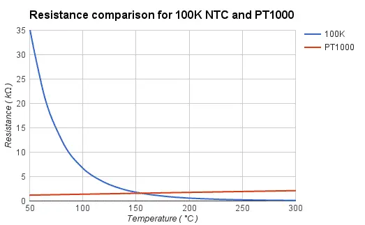
The difference between a linear sensor (RTD and thermocouple) and a non-linear sensor is mainly a programming concern. With a linear sensor, a simple first order formula ( Y = a*X+b ) can solve the temperature for a particular reading. However, using mathematics with a non-linear temperature sensor can get complicated.
The simplest solution is to make a table (Temperature vs Resistance) and let the firmware interpolate the temperature. This is actually also used for RTD sensor in many RepRap firmware.
Having a 10°C gap between values is a good compromise between memory usage and precision. 20°C gap is acceptable below 180°C since most plastics are printed at a higher temperature, precision isn’t critical.
Accuracy
The accuracy tells you how exact is your sensor reading. Taking a thermistor, a RTD and a thermocouple side by side while reading the same temperature will probably give three different results.
The RTD is the most accurate sensor of all three. Also, these sensors usually have very high tolerance thus making them interchangeable without too much trouble. Few thermistors are rated to match their accuracy. An accurate sensor will give the very similar results from one sensor to another. An inaccurate sensor will give a slight different results between sensor, so you might require to fine-tune the filament temperature to get the same results as the previous sensor.
This advantage applies mostly when a sensor breaks and must be changed. The main reason for sensor failure are broken leads due to improper sensor cable management. Make sure that your cables are well fixed when your printer is moving.
Sources
Control Engineering : Temperature tutorial
PT100 Probes Specification and Performance
3D Printed plastics properties
Response time comparison for RTDs

